OneFS and Provisioning Dell Technologies Connectivity Services – Part 2

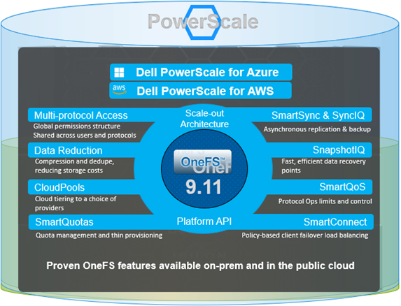
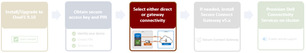
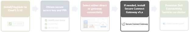
In the previous article in this Dell Technologies Connectivity Services (DTCS) for OneFS Support series, we reviewed the off-cluster prerequisites for enabling DTCS on a PowerScale cluster:

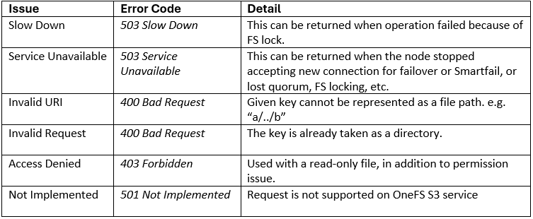
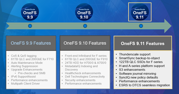
  1. Upgrading the cluster to OneFS 9.10 or later.
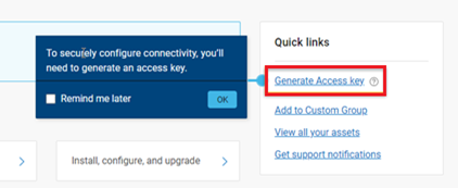
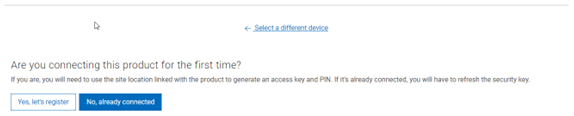
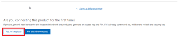
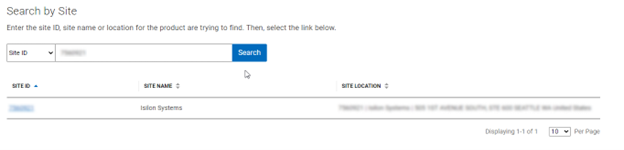
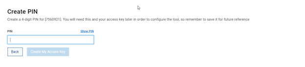
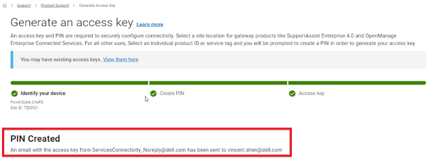
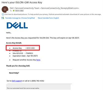
  2. Obtaining the secure access key and PIN.
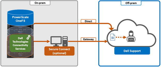
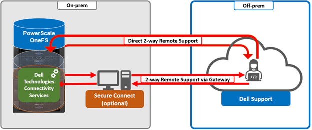
  3. Selecting either direct connectivity or gateway connectivity.
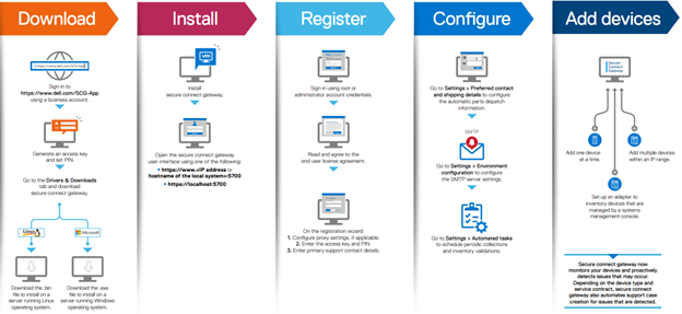
  4. If using gateway connectivity, installing Secure Connect Gateway v5.x.

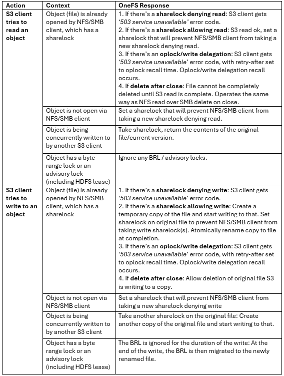
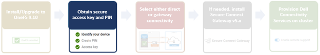
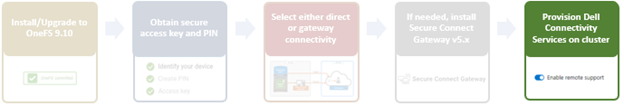
In this article, we turn our attention to step 5 – provisioning Dell Technologies Connectivity Services (DTCS) on the cluster.

Note that, as part of this process, we’ll be using the access key and PIN credentials previously obtained from the Dell Support portal in step 2 above.

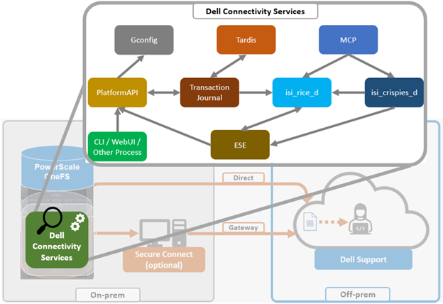
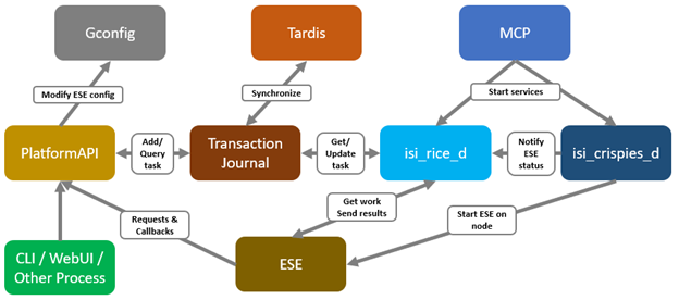
Provisioning DTCS on a cluster

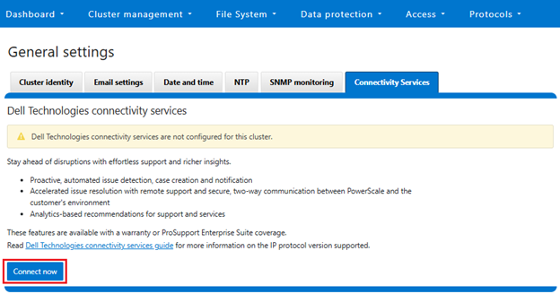
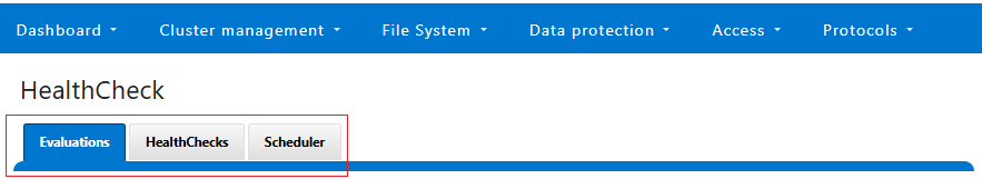
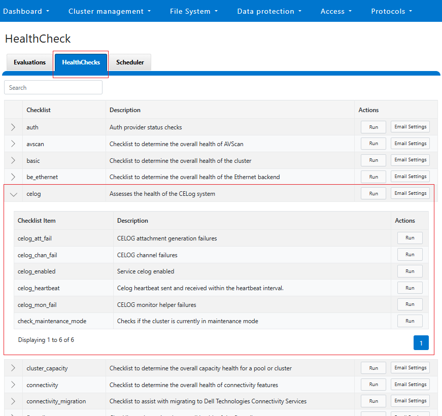
DTCS can be configured from the OneFS 9.10 WebUI by navigating to ‘Cluster management > General settings > DTCS’.

When unconfigured, the Connectivity Services WebUI page also displays verbiage recommending the adoption of DTCS:

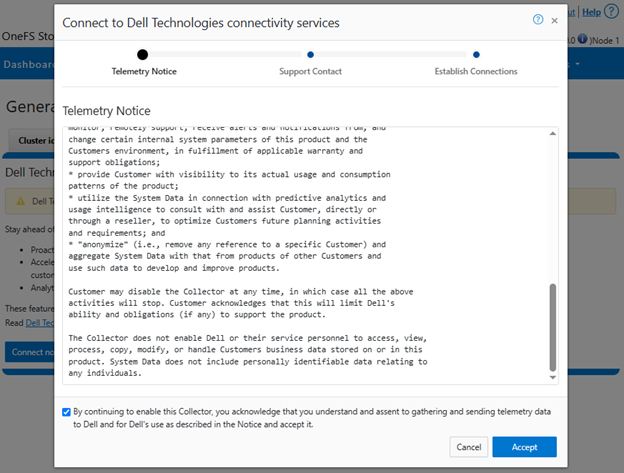
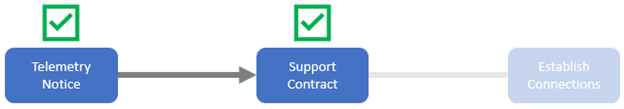
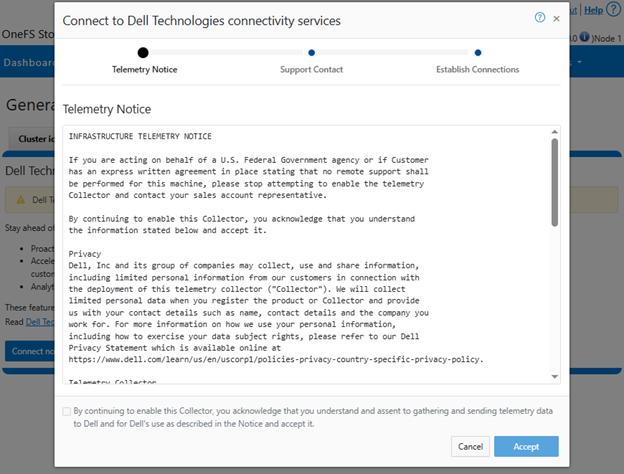
  1. Accepting the telemetry notice.

Selecting the ‘Connect Now’ button initiates the following setup wizard. The first step requires checking and accepting the Infrastructure Telemetry Notice:

  1. Support Contract.

For the next step, enter the details for the primary support contact, as prompted:

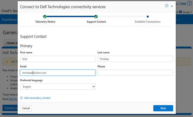
Or from the CLI using the ‘isi connectivity contacts’ command set. For example:

# isi connectivity contacts modify --primary-first-name=Nick --primary-last-name=Trimbee --primary-email=trimbn@isilon.com
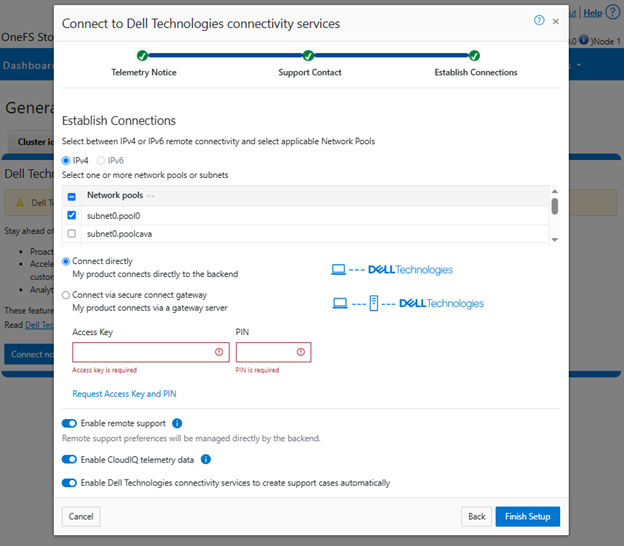
  1. Establish Connections.

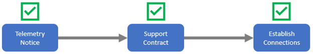
Next, complete the ‘Establish Connections’ page

This involves the following steps:

  • Selecting the network pool(s).
  • Adding the secure access key and PIN,
  • Configuring either direct or gateway access
  • Selecting whether to allow remote support, CloudIQ telemetry, and auto case creation.

a. Select network pool(s).

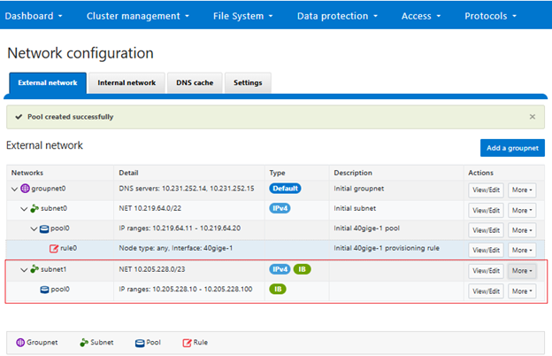
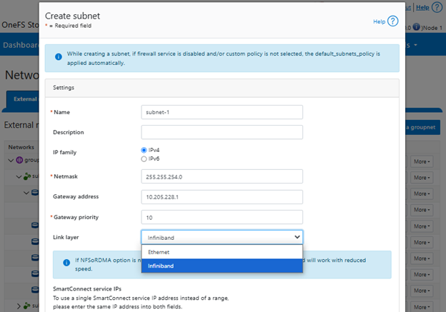
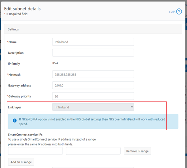
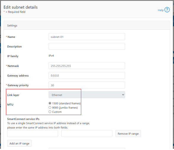
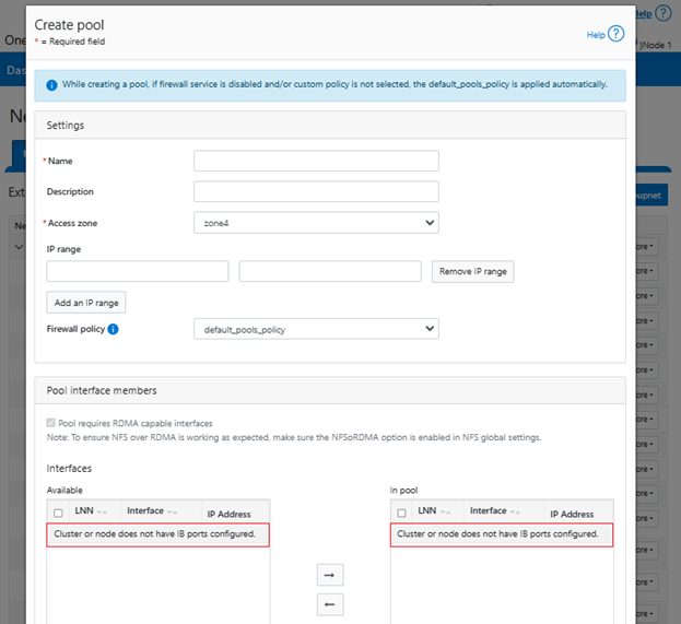
At least one statically-allocated IPv4 or IPv6 network subnet and pool is required for provisioning DTCS.

Select one or more network pools or subnets from the options displayed. For example, in this case ‘subnet0pool0’:

Or from the CLI:

Select one or more static subnet/pools for outbound communication. This can be performed via the following CLI syntax:

# isi connectivity settings modify --network-pools="subnet0.pool0"

Additionally, if the cluster has the OneFS network firewall enabled (‘isi network firewall settings’), ensure that outbound traffic is allowed on port 9443.

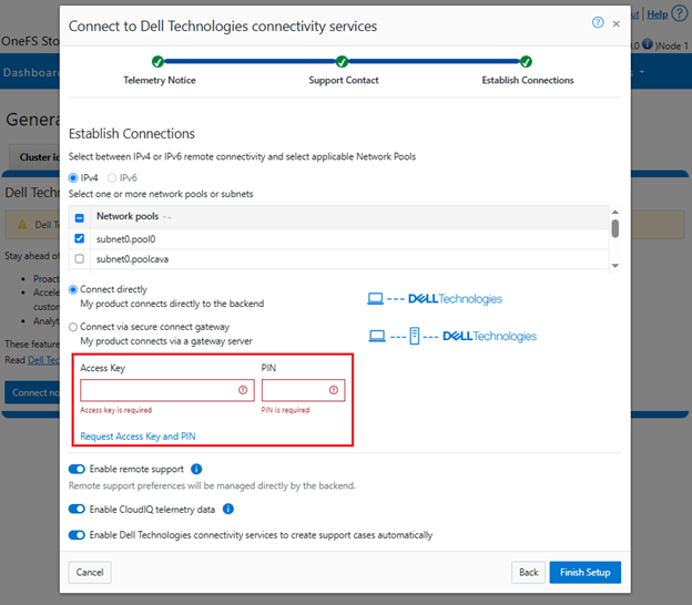
b.  Add secure access key and PIN.

In this next step, add the secure access key and pin. These should have been obtained in an earlier step in the provisioning procedure from the following Dell Support site: https://www.dell.com/support/connectivity/product/isilon-onefs.:

Alternatively, if configuring DTCS via the OneFS CLI, add the key and pin via the following syntax:

# isi connectivity provision start --access-key <key> --pin <pin>

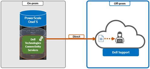
c.  Configure access.

i. Direct access.

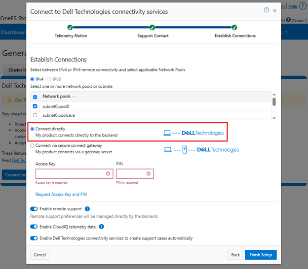
Or from the CLI. For example, to configure direct access (the default), ensure the following parameter is set:

# isi connectivity settings modify --connection-mode direct

# isi connectivity settings view | grep -i "connection mode"

Connection mode: direct
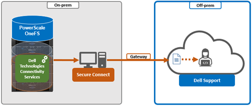
ii.  Gateway access.

Alternatively, to connect via a gateway, check the ‘Connect via Secure Connect Gateway’ button:

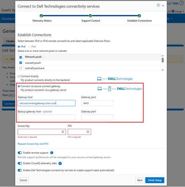
Complete the ‘gateway host’ and ‘gateway port’ fields as appropriate for the environment.

Alternatively, to set up a gateway configuration from the CLI, use the ‘isi connectivity settings modify’ syntax. For example, to configure using the gateway FQDN ‘secure-connect-gateway.yourdomain.com’ and the default port ‘9443’:

# isi connectivity settings modify --connection-mode gateway

# isi connectivity settings view | grep -i "connection mode"

Connection mode: gateway

# isi connectivity settings modify --gateway-host secure-connect-gateway.yourdomain.com --gateway-port 9443

When setting up the gateway connectivity option, Secure Connect Gateway v5.0 or later must be deployed within the data center. Note that DTCS is incompatible with either ESRS gateway v3.52 or SAE gateway v4. However, Secure Connect Gateway v5.x is backwards compatible with PowerScale OneFS ESRS and SupportAssist, which allows the gateway to be provisioned and configured ahead of a cluster upgrade to DTCS/OneFS 9.10.

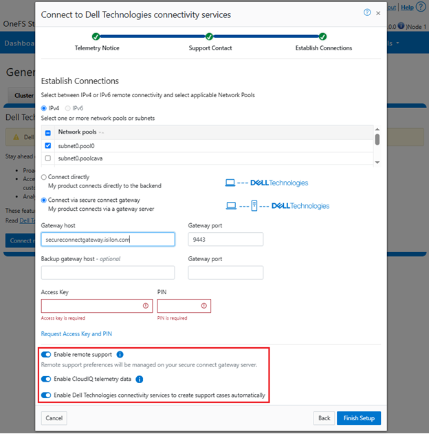
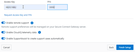
d.  Configure support options.

Finally, configure the desired support options:

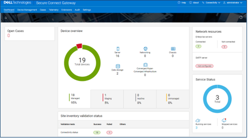
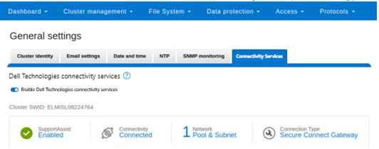
When complete, the WebUI will confirm that SmartConnect is successfully configured and enabled, as follows:
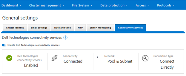
Or from the CLI:

# isi connectivity settings view

Service enabled: Yes

Connection State: enabled

OneFS Software ID: ELMISL0223BJJC

Network Pools: subnet0.pool0, subnet0.testpool1, subnet0.testpool2, subnet0.testpool3, subnet0.testpool4

Connection mode: gateway

Gateway host: eng-sea-scgv5stg3.west.isilon.com

Gateway port: 9443

Backup Gateway host: eng-sea-scgv5stg.west.isilon.com

Backup Gateway port: 9443

Enable Remote Support: Yes

Automatic Case Creation: Yes

Download enabled: Yes

Having worked through getting DTCS configured, up and running, in the next article in this series we’ll turn our attention to the management and troubleshooting of DTCS.

PowerScale OneFS 9.11

In the runup to next month’s Dell Technologies World 2025, PowerScale is bringing spring with the launch of the innovative OneFS 9.11 release, which shipped today (8th April 2025). This all-encompassing new 9.11 version offers PowerScale innovations in capacity, durability, replication, protocols, serviceability, and ease of use.

OneFS 9.11 delivers the latest version of PowerScale’s software platform for on-prem and cloud environments and workloads. This deployment flexibility can make it a solid fit for traditional file shares and home directories, vertical workloads like financial services, M&E, healthcare, life sciences, and next-gen AI, ML and analytics applications.

PowerScale’s scale-out architecture can be deployed on-site, in co-location facilities, or as customer managed Amazon AWS and Microsoft Azure deployments, providing core to edge to cloud flexibility, plus the scale and performance and needed to run a variety of unstructured workflows on-prem or in the public cloud.

With data security, detection, and monitoring being top of mind in this era of unprecedented cyber threats, OneFS 9.11 brings an array of new features and functionality to keep your unstructured data and workloads more available, manageable, and durable than ever.

Hardware Innovation

On the platform hardware front, OneFS 9.11 also unlocks dramatic capacity enhancements the all-flash F710 and F910, which see the introduction of support for 122TB QLC SSDs.

Additionally, support is added in OneFS 9.11 for future H and A-series chassis-based hybrid platforms.

Software Journal Mirroring

In OneFS 9.11 a new software journal mirroring capability (SJM) is added for the PowerScale all-flash F710 and F910 platforms with 61 TB or larger QLC SSDs. For these dense drive nodes, software journal mirroring negates the need for higher FEC protection levels and their associated overhead.

With SJM, file system writes are sent to a node’s local journal as well as synchronously replicated, or mirrored, to a buddy node’s journal. In the event of a failure, SJM’s automatic recovery scheme can use a Buddy journal’s mirrored contents to re-form the Primary node’s journal, avoiding the need to SmartFail the node.

Protocols

The S3 object protocol enjoys conditional write and cluster status enhancements in OneFS 9.11. With conditional write support, the addition of an ‘if-none-match’ HTTP header for ‘PutObject’ or ‘CompleteMultipartUpload’ requests guards against overwriting of existing objects with identical key names.

For cluster reporting, capacity, health, and network status are exposed via new S3 endpoints. Status monitoring is predicated on a virtual bucket and object, and reported via GETs on the virtual object to read the Cluster Status data. All other S3 calls to the virtual bucket and object are blocked, with 405 error code returned.

Replication

In OneFS 9.11, SmartSync sees the addition of backup-to-object functionality. This includes a full-fidelity file system baseline plus fast incremental replication to ECS/ObjectScale, AWS S3, and AWS Glacier IR object stores. Support is provided for the full range of OneFS path lengths, encodings, and file sizes up to 16TB – plus special files and alternate data streams (ADS), symlinks and hardlinks, sparse regions, and POSIX and SMB attributes.

OneFS 9.11 also introduces the default enablement of temporary directory hashing on new SyncIQ replication policies, thereby improving target-side directory delete performance.

Support and Monitoring

For customers that are still using Dell’s legacy ESRS connectivity service, OneFS 9.11 also includes a seamless migration path to its replacement, Dell Technologies Connectivity Services (DTCS). To ensure all goes smoothly, a pre-check phase runs a migration checklist, which must pass in order for the operation to progress. Once underway, the prior ESRS and cluster identity settings are preserved and migrated, and finally a provisioning phase completes the transition to DTCS.

In summary, OneFS 9.11 brings the following new features and functionality to the Dell PowerScale ecosystem:

Feature Description
Networking ·         Dynamic IP pools added to SmartConnect Basic
Platform ·         Support for F-series nodes with 122TB QLC SSD drives
Protocol ·         S3 cluster status API
Replication ·         SmartSync File-to-Object
Support ·         Seamless ESRS to DTCS migration


Reliability ·         Software Journal Mirroring for high-capacity QLC SSD nodes.

We’ll be taking a deeper look at the new OneFS 9.11 features and functionality in blog articles over the course of the next few weeks.

Meanwhile, the new OneFS 9.11 code is available on the Dell Support site, as both an upgrade and reimage file, allowing both installation and upgrade of this new release.

For existing clusters running a prior OneFS release, the recommendation is to open a Service Request with to schedule an upgrade. To provide a consistent and positive upgrade experience, Dell Technologies is offering assisted upgrades to OneFS 9.11 at no cost to customers with a valid support contract. Please refer to this Knowledge Base article for additional information on how to initiate the upgrade process.

OneFS and Provisioning Dell Technologies Connectivity Services – Part 1

In OneFS 9.10, several OneFS components leverage Dell Technologies Connectivity Services (DTCS) as their secure off-cluster data retrieval and communication channel. These include:

Component Details
Events and Alerts DTCS can send CELOG events and attachments via ESE to CLM.
Diagnostics Logfile gathers can be uploaded to Dell via DTCS.
License activation License activation uses DTCS for the ‘isi license activation start’ CLI cmd
Telemetry Telemetry is sent through DTCS to CloudIQ for analytics
Health check Health check definition downloads  leverage DTCS
Remote Support Remote Support  uses DTCS along with Connectivity Hub

For existing clusters, DTCS supports the same basic workflows as its predecessors, ESRS and SupportAssist, so the transition from old to new is generally pretty seamless.

As such, the overall process for enabling DTCS in OneFS is as follows:

  1. Upgrade the cluster to OneFS 9.10.
  2. Obtain the secure access key and PIN.
  3. Select either direct connectivity or gateway connectivity.
  4. If using gateway connectivity, install Secure Connect Gateway (v5.0 or later).
  5. Provision DTCS on the cluster.

We’ll go through each of the configuration steps above in order:

  1. Install or upgrade to OneFS 9.10.

First, the cluster must be running OneFS 9.10 in order to configure DTCS.

There are some additional considerations and caveats to bear in mind when upgrading to OneFS 9.10 and planning on enabling DTCS. These include the following:

  • DTCS is disabled when STIG Hardening applied to cluster
  • Using DTCS on a hardened cluster is not supported
  • Clusters with the OneFS network firewall enabled (‘isi network firewall settings’) may need to allow outbound traffic on ports 443 and 8443, plus 9443 if gateway (SCG) connectivity is configured.
  • DTCS is supported on a cluster that’s running in Compliance mode
  • If the cluster already has SupportAssist configured and running, the conversion to DTCS will occur automatically.
  • If upgrading from an earlier release on a cluster not running SupportAssist, the OneFS 9.10 upgrade to must be committed before DTCS can be provisioned.

Also, ensure that the user account that will be used to enable DTCS belongs to a role with the ‘ISI_PRIV_REMOTE_SUPPORT’ read and write privilege. For example:

# isi auth privileges | grep REMOTE

ISI_PRIV_REMOTE_SUPPORT                        Configure remote support

For example, the ‘ese’ user account below:

# isi auth roles view ConnectivityServicesRole

Name: ConnectivityServicesRole

Description: -

Members: ese

Privileges

ID: ISI_PRIV_LOGIN_PAPI

Permission: r


ID: ISI_PRIV_REMOTE_SUPPORT

Permission: w
  1. Obtaining secure access key and PIN.

An access key and pin are required in order to provision DTCS, and these secure keys are held in Key manager under the RICE domain. This access key and pin can be obtained from the Dell Support site:

In the Quick link navigation bar, select the ‘Generate Access key’ link:

On the following page, select the appropriate button:

The credentials required to obtain an access key and pin vary depending on prior cluster configuration. Sites that have previously provisioned ESRS will need their OneFS Software ID (SWID) to obtain their access key and pin.

The ‘isi license list’ CLI command can be used to determine a cluster’s SWID. For example:

# isi license list | grep "OneFS Software ID"

OneFS Software ID: ELMISL999CKKD

However, customers with new clusters and/or have not previously provisioned ESRS or SupportAssist will require their Site ID in order to obtain the access key and pin.

Note that any new cluster hardware shipping after January 2023 will already have a built-in key, so this key can be used in place of the Site ID above.

For example, if this is the first time registering this cluster and it does not have a built-in key, select ‘Yes, let’s register’:

Enter the Site ID, site name, and location information for the cluster:

Choose a 4-digit PIN and save it for future reference. After that click the ‘Create My Access Key’ button:

Next, the access key is generated.

An automated email is sent from the Dell Services Connectivity Team containing the pertinent key info, including:

  • Access Key
  • Product ID
  • Site ID/UCID
  • Expiration Date

For example:

Note that this access key is valid for one week, after which it automatically expires.

Next, in the cluster’s WebUI, navigate back to Cluster management > General settings > Connectivity Services and complete the EULA:

Next, enter the access key and PIN information in the appropriate fields. Finally, click the ‘Finish Setup’ button to complete the DTCS provisioning process:

  1. Direct or gateway topology decision.

A topology decision will need to be made between implementing either direct connectivity or gateway connectivity, depending on the needs of the environment:

  • Direct Connect:

  • Gateway Connect:

DTCS uses ports 443 and 8443 by default for bi-directional communication between the cluster and Connectivity Hub. As such, these ports will need to be open across any firewalls or packet filters between the cluster and the corporate network edge to allow connectivity to Dell Support.

Additionally, port 9443 is used for communicating with a gateway (SCG).

# grep -i esrs /etc/services

isi_esrs_d      9443/tcp  #EMC Secure Remote Support outbound alerts
  1. Optional Secure Connect Gateway installation.

This step is only required when deploying a Secure Connect gateway. If a direct connect topology is desired, go directly to step 5 below.

When configuring DTCS with the gateway connectivity option, Secure Connect Gateway v5.0 or later must be deployed within the data center.

Dell Secure Connect Gateway (SCG) is available for Linux, Windows, Hyper-V, and VMware environments, and as of writing, the latest version is 5.28.00. The installation binaries can be downloaded from: https://www.dell.com/support/home/en-us/product-support/product/secure-connect-gateway/drivers

The procedure to download SCG is as follows:

  1. Sign in to https://www.dell.com/support/product-details/en-us/product/secure-connect-gateway-app-edition. The Secure Connect Gateway – Application Edition page is displayed. If you have issues signing in using your business account or unable to access the page even after signing in, contact Dell Administrative Support.
  2. In the Quick links section, click Generate Access key.
  3. On the Generate Access Key page, perform the following steps:
  4. Select a site ID, site name, or site location.
  5. Enter a four-digit PIN and click Generate key. An access key is generated and sent to your email address. NOTE: The access key and PIN must be used within seven days and cannot be used to register multiple instances of secure connect gateway.
  6. Click Done.
  7. On the Secure Connect Gateway – Application Edition page, click the Drivers & Downloads tab.
  8. Search and select the required version.
  9. In the ACTION column, click Download.

The following steps are required in order to setup SCG:

Pertinent resources for configuring and running SCG include:

SCG Deployment Guide

SCP User Guide

SCP Support Matrix, for supported devices, protocols, firmware versions, and operating systems.

Another useful source of SCG installation, configuration, and troubleshooting information is the Dell support forum: https://www.dell.com/community/Secure-Connect-Gateway/bd-p/SCG

  1. Provisioning DTCS on the cluster.

At this point, the off-cluster pre-staging work should be complete.

In the next article in this series, we turn our attention to the DTCS provisioning process on the cluster itself (step 5).

OneFS Dell Technologies Connectivity Services Architecture and Operation

In this article in the Dell Technologies Connectivity Services series, we’ll dig a little deeper and look at the OneFS DTCS architecture and operation.

The OneFS Dell Connectivity Services relies on the following infrastructure and services:

Service Name
ESE Embedded Service Enabler.
isi_rice_d Remote Information Connectivity Engine (RICE).
isi_crispies_d Coordinator for RICE Incidental Service Peripherals including ESE Start.
Gconfig OneFS centralized configuration infrastructure.
MCP Master Control Program – starts, monitors, and restarts OneFS services.
Tardis Configuration service and database.
Transaction journal Task manager for RICE.

Of these, ESE, isi_crispies_d, isi_rice_d, and the Transaction Journal were introduced back in OneFS 9.5 and are exclusive to Dell Connectivity Services. In contrast, Gconfig, MCP, and Tardis are all legacy services that are employed by multiple other OneFS components.

The Remote Information Connectivity Engine (RICE) represents the Dell Connectivity Services ecosystem that allows OneFS to connect to the Dell support backend. At a high level, its architecture operates as follows:

Under the hood, the Embedded Service Enabler (ESE) is at the core of the connectivity platform and acts as a unified communications broker between the PowerScale cluster and Dell Support. ESE runs as a OneFS service and, upon startup, looks for an on-premises gateway server, such as Dell Connectivity Services Enterprise. If none is found, it connects back to the connectivity pipe (SRS). The collector service then interacts with ESE to send telemetry, obtain upgrade packages, transmit events and alerts, etc.

Depending on the available resources, ESE provides a base functionality with optional capabilities to enhance serviceability as appropriate. ESE is multithreaded, and each payload type is handled by different threads. For example, events are handled by event threads, and binary and structured payloads are handled by web threads. Within OneFS, ESE gets installed to /usr/local/ese and runs as the ese user in the ese group.

Networking-wise, Dell Connectivity Services  provides full support for both IPv4 and IPv6. The responsibilities of isi_rice_d include listening for network changes, getting eligible nodes elected for communication, monitoring notifications from CRISPIES, and engaging Task Manager when ESE is ready to go.

The Task Manager is a core component of the RICE engine. Its responsibility is to watch the incoming tasks that are placed into the journal and assign workers to step through the tasks state machine until completion. It controls the resource utilization (python threads) and distributes tasks that are waiting on a priority basis.

The ‘isi_crispies_d’ service exists to ensure that ESE is only running on the RICE active node, and nowhere else. It acts, in effect, like a specialized MCP just for ESE and RICE-associated services, such as IPA. This entails starting ESE on the RICE active node, re-starting it if it crashes on the RICE active node, and stopping it and restarting it on the appropriate node if the RICE active instance moves to another node. We are using ‘isi_crispies_d’ for this, and not MCP, because MCP does not support a service running on only one node at a time.

The core responsibilities of ‘isi_crispies_d’ include:

  • Starting and stopping ESE on the RICE active node
  • Monitoring ESE and restarting, if necessary. ‘isi_crispies_d’ restarts ESE on the node if it crashes. It will retry a couple of times and then notify RICE if it’s unable to start ESE.
  • Listening for gconfig changes and updating ESE. Stopping ESE if unable to make a change and notifying RICE.
  • Monitoring other related services.

The state of ESE, and of other RICE service peripherals, is stored in the OneFS tardis configuration database so that it can be checked by RICE. Similarly, ‘isi_crispies_d’ monitors the OneFS Tardis configuration database to see which node is designated as the RICE ‘active’ node.

The ‘isi_telemetry_d’ daemon is started by MCP and runs when Dell Connectivity Services is enabled. It does not have to be running on the same node as the active RICE and ESE instance. Only one instance of ‘isi_telemetry_d’ will be active at any time, while the other nodes wait for the lock.

The current status and setup of Dell Connectivity Services on a PowerScale cluster can be queried via the ‘isi connectivity settings view’ CLI command. For example:

# isi connectivity settings view

        Service enabled: Yes

       Connection State: enabled

      OneFS Software ID: ELMISL08224764

          Network Pools: subnet0:pool0

        Connection mode: direct

           Gateway host: -

           Gateway port: -

    Backup Gateway host: -

    Backup Gateway port: -

  Enable Remote Support: Yes

Automatic Case Creation: Yes

       Download enabled: Yes

This can also be viewed from the WebUI under Cluster management > General settings > Connectivity Services:

Note that once a cluster is provisioned with Dell Connectivity Services, the legacy ESRS can no longer be used.

OneFS and Dell Technologies Connectivity Services

Within the plethora of new functionality in the OneFS 9.10 release payload lies support for the Dell Technologies Connectivity Services, or DTCS – Dell’s remote connectivity system.

DTCS assists with quickly identifying, triaging, and fixing cluster issues, and boosts productivity by replacing manual routines with automated support. Its predictive issue detection and proactive remediation helps accelerate resolution – or avoid issues completely. Best of all, DTCS is included with all Dell PowerScale support plans, although the specific features available may vary based on the level of service contract.

Within OneFS, Dell Technologies Connectivity Services is intended for transmitting events, logs, and telemetry from PowerScale to Dell support. As such, it provides a full replacement for the legacy ESRS, as well as rebranding of the former SupportAssist services.

Delivering a consistent remote support experience across the storage portfolio, DTCS is intended for all sites that can send telemetry off-cluster to Dell over the internet. Dell Connectivity Services integrates the Dell Embedded Service Enabler (ESE) into PowerScale OneFS along with a suite of daemons to allow its use on a distributed system.

Dell Technologies Connectivity Services (formerly SupportAssist) ESRS
Dell’s next generation remote connectivity solution. Being phased out of service.
Can either connect directly, or via supporting gateways. Can only use gateways for remote connectivity.
Uses Connectivity Hub to coordinate support. Uses ServiceLink to coordinate support.
Requires access key and pin, or hardware key, to enable. Uses customer username and password to enable.

Dell Technologies Connectivity Services uses Connectivity Hub and can either interact directly, or through a Secure Connect gateway.

DTCS comprises a variety of components that gather and transmit various pieces of OneFS data and telemetry to Dell Support, via the Embedded Service Enabler (ESE).  These workflows include CELOG events, In-product activation (IPA) information, CloudIQ telemetry data, Isi-Gather-info (IGI) log sets, and provisioning, configuration and authentication data to ESE and the various backend services.

Workflow Details
CELOG DTCS can be configured to send CELOG events and attachments via ESE to CLM.   CELOG has a ‘Dell Connectivity Services’ channel that, when active, will create an EVENT task for DTCS to propagate.
License Activation The isi license activation start command uses DTCS to connect.

Several pieces of PowerScale and OneFS functionality require licenses, and to register and must communicate with the Dell backend services in order to activate those cluster licenses. In OneFS 9.10, DTCS is the preferred mechanism to send those license activations via the Embedded Service Enabler(ESE) to the Dell backend. License information can be generated via the ‘isi license generate’ CLI command, and then activated via the ‘isi license activation start’ syntax.

Provisioning DTCS must register with backend services in a process known as provisioning.  This process must be executed before the Embedded Service Enabler(ESE) will respond on any of its other available API endpoints.  Provisioning can only successfully occur once per installation, and subsequent provisioning tasks will fail. DTCS must be configured via the CLI or WebUI before provisioning.  The provisioning process uses authentication information that was stored in the key manager upon the first boot.
Diagnostics The OneFS isi diagnostics gather and isi_gather_info logfile collation and transmission commands have a –connectivity option.
Healthchecks HealthCheck definitions are updated using DTCS.
Telemetry CloudIQ Telemetry data is sent using DTCS.
Remote Support Remote Support uses DTCS and the Connectivity Hub to assist customers with their clusters.

DTCS requires an access key and PIN, or hardware key, in order to be enabled, with most customers likely using the access key and pin method. Secure keys are held in Key manager under the RICE domain.

In addition to the transmission of data from the cluster to Dell, Connectivity Hub also allows inbound remote support sessions to be established for remote cluster troubleshooting.

In the next article in this series, we’ll take a deeper look at the Dell Technologies Connectivity Services architecture and operation.

OneFS Healthcheck Enhancements

As the name suggests, PowerScale OneFS healthchecks enable a storage administrator to quickly and easily evaluate the status of specific software and hardware components of the cluster and its environment.

The OneFS 9.10 release includes several healthcheck enhancements, which aid cluster administrator in quickly understanding the health of the system, plus offering resolution guidance in the event of a failure. In a nutshell, these include:

Function Details
Dashboard Display current healthcheck results in the landing page to indicate the current health of the system (Real-time health of the system).
Export The ability to export in CSV or JSON formats.
Grouping Grouping of healthcheck based on category, frequency.
History Historical healthchecks presented as a separate category.
Links Links provided to relevant knowledge base (KB) articles instead of plain texts.
Troubleshooting Detailed information on the failure and troubleshooting guidance.

The healthcheck landing page in OneFS 9.10, accessible under Cluster Management > Healthchecks, displays navigation tabs for three pages:

Of these, the ‘evaluation’ and ‘heathcheck’ views are enhanced in the new release, with ‘Evaluations’ being the default landing page.

In earlier versions, the ‘healthcheck’ page, under Cluster Management > Healthchecks > Healthchecks, displayed two separate tables – one for checklists themselves and another for their contents, the checklist items. Plus, there was no properly directed relationship between the checklists and their items.

To address this, OneFS 9.10 condenses these into a single table view, where each checklist row can be expanded to make its associated items visible. For example, the expanded CELOG checklist and contents in the following:

Moving to a single table format has also enabled the addition of keyword search functionality. As the desired search string is entered into the search box, the WebUI automatically expands and collapses rows to make the matching content visible. This allows the admin to quickly drill down into their checks of interest, and then easily run the full checklist – or just individual items themselves. For example, searching for ‘quota’ reveals the following related items within the ‘auth’ and ‘basic’ checklists:

Additionally, the email settings button for each healthcheck are now more apparent, intuitive, and accessible, offering either default or custom distribution list options:

For ‘evaluations’, the enhanced Healthcheck dashboard in OneFS 9.10 clearly displays the current healthcheck status and results on the landing page. As such, navigating to Cluster Management > Healthchecks now provides a single screen synopsis of the real-time health of the cluster. For example:

In addition to a keyword search option, this view can also be filtered by the ‘latest’ evaluation, or ‘all’ evaluations.

Under the ‘Actions’ field, the ‘More’ dropdown allows logs to be easily gathered and/or downloaded:

If a log gather is selected, its progress is reported is the ‘status’ field for the associated check. For example:

Clicking the ‘view details’ button for a particular failed checklist opens up a pane with both ‘passed’ and ‘failed’ items:

The ‘passed items’ tab provides details on the specific check(s) that were successfully completed (or unsupported) in the evaluation run.

Similarly, the ‘failed items’ tab displays the unsuccessful check(s) with their error description. For example, the following job engine healthcheck, notifying of LIN-based jobs and suggesting remediation steps:

In this case, even though 260 of the checklist items have passed and only 1 has failed, the overall status for the ‘basic’ checklist is ‘failed’.

The ‘export’ drop-down allows the healthcheck error details to be exported for further analysis as either a CSV or JSON file. For example:

Similarly, the OneFS 9.10 CLI also has a ‘format’ option for exporting healthcheck evaluations. However, unlike the WebUI, the command line options include a list and table format, in addition to CSV and JSON. As such, the 9.10 Healthcheck export options can be summarized as follows:

Export Format CLI WebUI
CSV x x
JSON x x
List x
Table x

The CLI syntax for specifying the export format is as follows:

# isi healthcheck evaluations view <id> --format <csv | json | list | table>

For example, to limit the view to one basic evaluation, in table format, and without the header and footer:

# isi healthcheck evaluations view basic20250304T1105 --format table --limit 1 --no-header --no-footer

basic20250304T1105 basic -    Completed Fail

WARNING    75  [NODE   5] port_flapping

 * Network port flapping has been detected at some point in the

   last 24 hours on the following ports mce0, mce1. This can cause

   issues such as memory leaks if not addressed. Contact Dell

   Technologies Support if you are experiencing network issues.

Note that the default output contains failing items for that evaluation only. However, the ‘—verbose’ flag can be included to display all the pass and fail items for that evaluation.

On the platform API (pAPI) front, the following new v21 endpoints have been added in OneFS 9.10:

/21/healthcheck/evaluations

This now includes the ‘format_for_csv_download’ option, and is used to enable CSV download of a healthcheck evaluation.

There’s also a new endpoint to track the status of a log gather in progress:

/21/cluster/diagnostics/gather/status

For example:

# curl -k https://<name>:<Passwd>@localhost:8080/platform/21/cluster/diagnostics/gather/status
{
"gather" :
{
"item" : null,
"path" : "/ifs/data/Isilon_Support/pkg",
"status" :
{
"Active_Status" : "RUNNING",
"Last_Status" : " NOT_RUNNING "
}
}
}

OneFS Front-end Infiniband Configuration

In the previous article in this series, we examined the ‘what’ and ‘why’ of front-end Infiniband on a PowerScale cluster. Now we turn our attention to the ‘how’ – i.e. the configuration and management of front-end IB.

The networking portion of the OneFS WebUI has seen some changes in 9.10, and cluster admins now have the flexibility to create either Ethernet or InfiniBand (IB) subnets. Depending on the choice, the interface list, pool and rule details automatically adjust to match the selected link layer type. This means that if Infiniband (IB) is selected, the interface list and pool details will update to reflect settings specific to IB, including a new ‘green pill’ icon to indicate the presence of IB subnets and pools on the external network table. For example:

Similarly, the subnet1 view from the CLI, with the ‘interconnect’ field indicating ‘Infiniband’:

# isi network subnets view subnet1
              ID: groupnet0.subnet1
            Name: subnet1
        Groupnet: groupnet0
           Pools: pool-infiniband
     Addr Family: ipv4
       Base Addr: 10.205.228.0
            CIDR: 10.205.228.0/23
     Description: Initial subnet
         Gateway: 10.205.228.1
Gateway Priority: 10
    Interconnect: Infiniband
             MTU: 2044
       Prefixlen: 24
         Netmask: 255.255.254.0
SC Service Addrs: 1.2.3.4
 SC Service Name: cluster.tme.isilon.com
    VLAN Enabled: False
         VLAN ID: -

Alternatively, if Ethernet is chosen, the relevant subnet, pool, and rule options for that topology are displayed.

This dynamic adjustment ensures that only the relevant options and settings for the configured network type are displayed, making the configuration process more intuitive and streamlined.

For example, to create an IB subnet under Cluster management > Network configuration > External network > Create subnet:

Or from the CLI:

# isi network subnets create groupnet0.subnet1 ipv4 255.255.254.0 --gateway --gateway-priority 10 10.205.228.1 --linklayer infiniband

Similarly, editing an Infiniband subnet:

Note that an MTU configuration option is not available when configuring an Infiniband subnet. Also, the WebUI displays a banner warning that NFS over Infiniband will operate at a reduced speed if NFS over RDMA has not already been enabled.

In contrast, editing an Ethernet subnet provides the familiar MTU frame-size configuration options:

A font-end network IP pool can be easily created under a subnet. For example from the CLI, using the ‘<groupnet>.<subnet>.<pool>’ notation:

# isi network pools create groupnet0.infiniband1.ibpool1

Or via the WebUI:

Adding an Infiniband subnet is permitted on any cluster, regardless of its network configuration. However, the above messages will be displayed if attempting to create a pool under an Infiniband subnet on a cluster or node without any configured front-end IB interfaces.

From the CLI, the ‘isi_hw_status’ utility can be used to easily verify a node’s front and back-end networking link layer types. For example, take the following F710 configuration:

The ‘isi_hw_status’ CLI command output also confirms the front-end network ‘FEType’ parameter, in this case as ‘Infiniband’:

# isi_hw_status
  SerNo: FD7LRY3
 Config: PowerScale F710
ChsSerN: FD7LRY3
ChsSlot: n/a
FamCode: F
ChsCode: 1U
GenCode: 10
PrfCode: 7
   Tier: 16
  Class: storage
 Series: n/a
Product: F710-1U-Dual-512GB-2x1GE-2x100GE QSFP28-2x200GE QSFP56-38TB SSD
  HWGen: PSI
Chassis: POWEREDGE (Dell PowerEdge)
    CPU: GenuineIntel (2.60GHz, stepping 0x000806f8)
   PROC: Dual-proc, 24-HT-core
    RAM: 549739036672 Bytes
   Mobo: 071PXR (PowerScale F710)
  NVRam: NVDIMM (SDPM VOSS Module) (8192MB card) (size 8589934592B)
 DskCtl: NONE (No disk controller) (0 ports)
 DskExp: None (No disk expander)
PwrSupl: PS1 (type=AC, fw=00.1D.9C)
PwrSupl: PS2 (type=AC, fw=00.1D,9C)
  NetIF: bge0,bge1,lagg0,mce0,mce1,mce2,mce3,mce4
 BEType: Infiniband
 FEType: 200GigE
 LCDver: IsiVFD3 (Isilon VFD V3)
 Midpln: NONE (No FCB Support)
Power Supplies OK

In contrast, the back-end network on this F710 is 200Gb Ethernet, as reported by the ‘BEType’ parameter.

From the node cabling perspective, the interface assignments on the rear of the F710 are as follows:

Additionally, the ‘mlxfwmanager’ CLI utility can be helpful for gleaning considerably more detail on a node’s NICs, including firmware versions, MAC address, GUID, part number, etc. For example:

# mlxfwmanager

Querying Mellanox devices firmware ...

Device #1:
----------
  Device Type:      ConnectX6
  Part Number:      ORRM24_Ax
  Description:      Nvidia ConnectX-6 VPI adapter card; HDR IB (200Gb/s) and 200GbE; dual-port QSFP56; PCIe4.0 x16
  PSID:             DEL0000000052
  PCI Device Name:  pci0:13:0:0
  Base MAC:         59a2e18dfdac
  Versions:         Current        Available
     FW             20.39.1002     N/A
     PXE            3.7.0201       N/A
     UEFI           14.32.0012     N/A
  Status:           No matching image found

Device #2:
----------
  Device Type:      ConnectX6DX
  Part Number:      OF6FXM_08P2T2_Ax
  Description:      Mellanox ConnectX-6 Dual Port 100 GbE QSFP56 Network Adapter
  PSID:             DEL0000000027
  PCI Device Name:  pci0:139:0:0
  Base GUID:        e8ebd30300060684
  Base MAC:         e8ebd3060684
  Versions:         Current        Available
     FW             22.36.1010     N/A
     PXE            3.6.0901       N/A
     UEFI           14.29.0014     N/A
  Status:           No matching image found

Device #3:
----------
  Device Type:      ConnectX6
  Part Number:      ORRM24_Ax
  Description:      Nvidia ConnectX-6 VPI adapter card; HDR IB (200Gb/s) and 200GbE; dual-port QSFP56; PCIe4.0 x16
  PSID:             DEL0000000052
  PCI Device Name:  pci0:181:0:0
  Base MAC:         a088c2ec499e
  Base GUID:        a088c20300ec499a
  Versions:         Current        Available
     FW             22.39.1002     N/A
     PXE            3.7.0201       N/A
     UEFI           14.32.0012     N/A
  Status:           No matching image found

In the example above, ‘Device #1’ is the back-end NIC, ‘Device #2’ is the 100Gb Ethernet ConnectX6 DX NIC in the PCIe4 slot, and ‘Device #3’ is the front-end Infiniband ConnectX6 VPI NIC in the primary PCIe5 slot.

There are a couple of caveats to be aware of when using front-end Infiniband on F710 and F910 node pools:

  • Upon upgrade to OneFS 9.10, any front-end Infiniband interfaces will only be enabled once the new release is committed.
  • Network pools created within Infiniband subnets will have their default ‘aggregation mode’ set to ‘unset’. Furthermore, this parameter will not be modifiable.
  • Since VLANs are not supported on Infiniband, OneFS includes validation logic to prevent this.

OneFS and Front-end Infiniband Networking

A number of scientific computing and commercial HPC customers use Infiniband as their principal network transport, and to date have used Infiniband bridges and gateways to connect their IB-attached compute server fleets to their PowerScale clusters. To address this, OneFS 9.10 introduces support for low latency HDR Infiniband front-end network connectivity on the F710 and F910 all-flash platforms, providing up to 200Gb/s of bandwidth with sub-microsecond latency. This can directly benefit generative AI and machine learning environments, plus other workloads –  particularly those involving highly concurrent streaming reads and writes.

In conjunction with the OneFS multipath driver, plus GPUDirect support, the choice of either HDR Infiniband or 200Gig Ethernet can satisfy the networking and data requirements of demanding technical workloads, such as autonomous driving model training, seismic analysis, and complex transformer-based AI workloads, and deep learning systems.

Specifically, this new functionality expands cluster front-end connectivity to include Infiniband, in addition to Ethernet, and enables the use of IP over IB and NFSoRDMA over IB.

With its debut in OneFS 9.10, front-end IB support is currently offered on both the PowerScale F710 and F910 all-flash nodes:

These two platforms can now host a Mellanox  CX-6 VPI NIC configured for HDR Infiniband in the primary front-end PCI slot, plus a CX-6 DX NIC configured for Ethernet in the secondary front-end PCI slot. This is worth noting, since in an ethernet only node, the primary port is typically used for Gb Ethernet, while the secondary slot is unpopulated. For performance reasons, this configuration ensures that the primary interface makes use of the full bandwidth of the Gen5 PCIe slot, while the secondary slot offers PCIe Gen4 connectivity, which limits it to 100Gb. Additionally, in OneFS 9.10, the node’s backend network, used for intra-cluster communication, can also now be configured for either HDR Infiniband or 200Gb Ethernet.

Prior to OneFS 9.10, there were several components within OneFS that assumed Infiniband was synonymous with only the backend network. This included the platform support interface (PSI) that is used to get information on the running platform, and which contained a single ‘network.interfaces.infiniband‘ key for Infiniband in OneFS 9.9 and earlier releases. To rectify this, the psi.conf in OneFS 9.10 now includes a pair of ‘network.interfaces.infininband.frontend’ and ‘network.interfaces.infiniband.backend’ keys, mirroring the corresponding key pair for the ethernet front and backend networks.

Here’s the rear view of both the F710 and 910 platforms, showing the slot locations of the front and back-end NICs in the Infiniband configuration. Note that both F710 and F910 nodes configured with Infiniband frontend support are automatically shipped with both an HDR IB card in the primary front-end slot (red) and a 100Gb Ethernet NIC in the secondary front-end slot.

F710

F910

Note that the PowerScale F210 does not support either front-end Infiniband, or 200Gig Ethernet at this point.  However, this is not a platform constraint, but rather a qualification effort limitation.

However, OneFS 9.10 does provides support for either backend HDR Infiniband or 200Gb Ethernet on all the current F-series platforms, including the  F210 node.

Backend HDR Infiniband support is again using the venerable CX-6 VPI 200Gb NIC, paired with the Quantum QM8790 IB switch, and using supplied 200Gb HDR cables.

Note though, that the QM 8790 switch only provides 40 HDR ports, and breakout cables are not currently supported. So, for now, an F-series cluster with an IB backend running OneFS 9.10 will be limited to a maximum of forty nodes. It’s also worth mentioning that the QM 8790 switch does support lower IB data rates such as QDR and FDR, and has also been qualified with the legacy CX3 VPI NICs and IB cables for legacy IB cluster compatibility and migration purposes.

From the CLI, the isi_hw_status command can be used to report on a node’s front and back-end networking types. For example, the following output from an F710 shows the front-end  network ‘FEType’ parameter as ‘Infiniband’.

# isi_hw_status | grep Type
BEType: Infiniband
FEType: 200GigE

However, the back-end network on this F710 is 200Gb Ethernet, as reported by the ‘BEType’ parameter.

In the next article in this series, we’ll look at the configuration and management of front-end Infiniband in OneFS 9.10

OneFS OpenSSL 3 and TLS 1.3 Support

Secure Sockets Layer (SSL) protocols use cryptographic algorithms to encrypt data, reducing the potential for unauthorized individuals or bad actors to intercept or tamper with the data. This is achieved through three principle and complimentary methods:

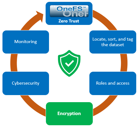
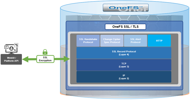
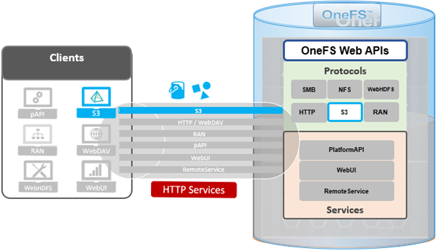
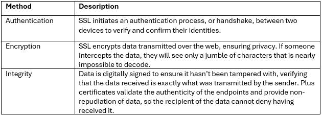
 When using either the OneFS WebUI or platform API (pAPI), all communication sessions are encrypted using SSL and the related Transport Layer Security (TLS). As such, SSL and TLS play a critical role in PowerScale’s Zero Trust architecture by enhancing security via encryption, validation, and digital signing.

In OneFS 9.10, OpenSSL has been upgraded from version 1.0.2 to version 3.0.14. This makes use of the newly validated OpenSSL 3.0.9 FIPS module, which is the latest version that has been blessed by the OpenSSL upstream project, and which is supported through September 2026.

Architecturally, SSL comprises four fundamental layers:

These reside within the stack as follows:

The basic handshake process begins with a client requesting an HTTPS WebUI session to the cluster. OneFS then returns the SSL certificate and public key. The client creates a session key, encrypted with the public key it’s received from OneFS. At this point, the client only knows the session key and it sends this encrypted session key to the cluster, which decrypts it using the private key. Now, both the client and OneFS know the session key so the session, encrypted via the symmetric key, can be established. OneFS automatically defaults to the best supported version of SSL, based on the client request.

As part of the OneFS 9.10 SSL upgrade, there’s a new implementation of FIPS mode that is compatible with OpenSSL 3, which all of the OneFS daemons make use of. But probably the most significant enhancement in the OpenSSL 3 upgrade is addition of library support for the TLS 1.3 ciphers, which are designed to meet the stringent Federal data-in-flight security requirements.  The OpenSSL 3 upgrade also deprecates and removes some legacy algorithms as well, so those will no longer be supported and can be removed entirely from OneFS in the future. More detail is available in the OpenSSL 3 Migration Guide, which contains an exhaustive list of every changes that was made in OpenSSL 3.

In OneFS 9.10 the TLS 1.2 cipher configuration remains the same as in OneFS 9.9, except that three TLS 1.3 ciphers are added:

  • TLS_AKE_WITH_AES_256_GCM_SHA384
  • TLS_AKE_WITH_CHACHA20_POLY1305_SHA256
  • TLS_AKE_WITH_AES_128_GCM_SHA256

Similarly, if FIPS mode is enabled, the same TLS 1.2 ciphers are available plus two TLS 1.3 ciphers are added:

  • TLS_AKE_WITH_AES_256_GCM_SHA384
  • TLS_AKE_WITH_AES_128_GCM_SHA256

There are no changes to the data path Apache HTTPD ciphers, so no addition of TLS 1.3 there – it still uses the same TLS 1.2 ciphers.

OneFS 9.10 also contains some changes to the SSH cryptography. So with FIPS mode disabled, the encryption algorithms, host key algorithms, or message authentication code algorithms all remain the same as in OneFS 9.9. however, support for the following four key exchange algorithms has been removed in 9.10:

  • diffie-hellman-group-exchange-sha256
  • diffie-hellman-group16-sha512
  • diffie-hellman-group18-sha512
  • diffie-hellman-group14-sha256

Similarly, with FIPS mode enabled, there are also no changes to encryption algorithms, source key, or message authentication codes. But support is removed for the following two key exchange algorithms.

  • diffie-hellman-group-exchange-sha256
  • diffie-hellman-group14-sha256

Note that the sha512 algorithms weren’t previously supported by FIPS mode anyway.

Moving on to TLS 1.3 phase one, OneFS 9.10 adds TLS 1.3 support for the WebUI and KMIP key management servers. Plus 9.10 also verifies that 1.3 is supported for the LDAP provider, for CELOG alert emails, for audit event and syslog forwarding, for the platform API and WebUI single sign-on, and also for SyncIQ.

Here’s a list of the capabilities:

Note that the OneFS components that aren’t explicitly called out in the table above likely won’t support TLS 1.3 currently, but are candidates to be uprev’d in a future phase of OneFS TLS 1.3 enablement.

The TLS 1.3 phase 1 enhancement in OneFS 9.10 allows the above components to negotiate either a TLS 1.2 or TLS 1.3 connection. The negotiated TLS version depends on the configuration of the environment. So if client supporting both TLS 1.2 and 1.3 are present, then the cluster will automatically negotiate and use TLS 1.3 where possible, but it will fall back to 1.2 for clients that only support that level. Similarly TLS 1.3 exclusively for environments with all 1.3 clients. For the curious or paranoid, it’s worth noting that the only way to verify which version of TLS is being used is via packet inspection. So if you really need to know, grabbing and analyzing packet captures will be your friend here.

There are a couple of other idiosyncrasies with TLS 1.3 support in OneFS 9.11 that also bear mentioning.

  • It’s not always possible to explicitly specify the minimum TLS protocol version currently since OneFS 9.10 does not expose these configuration options. This means that clients and servers on OneFS will decide automatically which version to use, and they should prefer 1.3.
  • OneFS 9.10 does not allow customers to disable TLS 1.3 ciphers, but this should not be an issue since all the 1.3 ciphers are still considered very secure.
  • OneFS also does not provide diagnostic information about which protocol version of TLS is in use. So in order to verify for certain that the cluster and/or client(s) are using a specific version of TLS, it will likely require taking and analyzing packet captures.

OneFS S3 Protocol and Concurrent Object Access

Among the array of PowerScale’s core unstructured data protocols lies the AWS S3 API – arguably the gold standard for object protocols. This enables the PowerScale data lake to natively support workloads which both write data via file protocols such as NFS, HDFS or SMB, and then read that same data as S3 objects, and vice versa.

Since OneFS S3 objects and buckets are essentially files and directories at the file system level, the same PowerScale data services, such as snapshots, replication, WORM immutability, tiering, etc, are all seamlessly integrated. So too are identity and permissions management and access controls across both the file and object realms.

This means that applications and workloads have multiple access options – across both file and object, and with the same underlying dataset, semantics, and services. This has the considerable benefit of eliminating the need for replication or migration of data for different access requirements, thereby vastly simplifying data and workload management. OneFS supports HTTPS/TLS, to meet organizations’ security, in-flight encryption, and compliance needs. Additionally, since S3 is integrated into OneFS as a top-tier protocol, it offers a high level of performance, similar to that of the SMB protocol.

By default, the S3 service listens on port 9020 for HTTP and 9021 for HTTPS, although both these ports are easily configurable. Within a PowerScale cluster, OneFS runs on and across all nodes equally, so no one node controls or ‘masters’ the cluster and all nodes are true peers. Looking from a high-level at the components within each node, the I/O stack is split into a top layer, or initiator, and a bottom layer, or participant. This division is used as a logical model for the analysis of OneFS’ read and write paths.

At a physical-level, the CPUs and memory cache within the nodes simultaneously handle both initiator and participant tasks for I/O taking place throughout the cluster.

For clarity’s sake, the level of detail that includes the caches and distributed lock manager has been omitted from the above.

When a client connects to a node’s protocol head to perform a write, it is interacting with the logical ‘top half’, or initiator, of that node. Any files or objects that are written by the client are broken into smaller logical chunks, or stripes, before being written to the logical ‘bottom half’, or participant, of a node, where the storage drives reside. Failure-safe buffering (write coalescer and journal) ensures that writes are efficient and read-modify-write operations are avoided. OneFS stripes data across all nodes and protects the files, directories and associated metadata via software erasure-code or mirroring.

File and object locking allows multiple users or processes to access data via a variety of protocols concurrently and safely. Since all nodes in an PowerScale cluster operate on the same single-namespace file system simultaneously, it requires mutual exclusion mechanisms to function correctly. For reading data, this is a fairly straightforward process involving shared locks. With writes, however, things become more complex and require exclusive locking, since data must be kept consistent.

Under the hood, the ‘bottom half’ locks OneFS uses to provide consistency inside the file system (internal) are separate from the ‘top half’ protocol locks that manage concurrency across applications (external). This allows OneFS to move a file’s metadata and data blocks around while the file itself is locked by an application. This is the premise of OneFS auto-balancing, reprotecting and tiering, where the restriper does its work behind the scenes in small chunks to minimize disruption.

The OneFS distributed lock manager (DLM) marshals locks across all the nodes in a storage cluster, allowing for multiple lock types to support both file system locks as well as cluster-coherent protocol-level locks. The DLM distributes the lock data across all the nodes in the cluster. In a mixed cluster, the DLM also balances memory utilization so that the lower-power nodes are not bullied.

Every node in a cluster is a coordinator for locking resources. A coordinator is assigned to lockable resources based on a hashing algorithm, designed so that the coordinator almost always ends up on a different node than the initiator of the request. When a lock is requested for a file/object, it could be either a shared or exclusive lock. Read requests are typically serviced by shared locks, allowing multiple users to simultaneously access the resource, whereas exclusive locks constrain to just one user at any given moment, typically for writes.

Here’s an example of how different nodes could request a lock from the coordinator:

  1. Thread 1 from node 4 and thread 2 from node 3 simultaneously request a shared lock on a file from the coordinator on node 2.
  2. Since no exclusive locks exist, node 2 grants shared locks, and nodes 3 and 4 read the requested file.
  3. Thread 3 from node 1 requests an exclusive lock for the same file that’s being read by nodes 3 and 4.
  4. Nodes 3 and 4 are still reading, so the coordinator (node 2) asks thread 3 from node 1 to wait.
  5. Thread 3 from node 1 blocks until the exclusive lock is granted by the coordinator (node 2) and then completes its write operation.

As such, an S3 client can access, read, and write to an object using HTTP GET and PUT requests, while other file protocol and/or S3 clients also access the same resource. OneFS supports two methods of specifying buckets and objects in a URL:

  • Path-style requests, using the first slash-delimited component of the request-URI path. For example:

https://tme1.isilon.com:9021/bkt01/lab/object1.pdf

  • Virtual hosted-style requests, specifying a bucket via the HTTP Host header. I.e.:

https://bkt01.tme.isilon.com:9021/lab/object1.pdf

Additionally, the principal API operations that OneFS supports include:

Essentially, this includes the basic bucket and object create, read, update, delete, or CRUD, operations, plus multipart upload.

As for client access, from the cluster side the general OneFS S3 operation flow can be characterized as follows:

  1. First, an S3 client or application establishes a connection to the cluster, with SmartConnect resolving the IP address with bucket name.
  2. OneFS creates a socket/listener with the appropriate TLS handling, as required.
  3. Next, OneFS (libLwHttp) receives and unmarshals the HTTP request/stream to determine the S3 request payload.
  4. Authorization and authentication is performed for bucket and object access.
  5. Next, the S3 request is queued for LwSched, which dispatches the work with the appropriate threading mode.
  6. The S3 protocol driver handles the operational logic and calls the IO manager (Lwio).
  7. Lwio manages any audit filter driver activity before and after the operation, while FSD (file system driver) handles the file system layer access.
  8. Finally, the S3 protocol driver creates an HTTP response with its operation result, which is returned to the S3 client via libLwHttp.
  9. Then back to step 3 for the next HTTP request, etc.

If a client HTTP request is invalid, or goes awry, OneFS follows the general AWS S3 error codes format – albeit with modifications to remove any AWS-specific info. The OneFS S3 implementation also includes some additional error codes for its intrinsic behaviors. These include:

So how do things work when clients try to simultaneous access the same file/object on a cluster via both file and object protocols? Here’s the basic flow describing OneFS cross-protocol locking: