OneFS SmartFail

OneFS protects data stored on failing nodes or drives in a cluster through a process called Smartfail. During the process, OneFS places a device into quarantine and, depending on the severity of the issue, the data on it into a read-only state. While a device is quarantined, OneFS reprotects the data on the device by distributing the data to other devices.

After all data eviction or reconstruction is complete, OneFS logically removes the device from the cluster and the node or drive can be physically replaced. OneFS only automatically Smartfails devices as a last resort. Nodes and/or drives can also be manually Smartfailed. However, it is strongly recommended to first consult Dell Technical Support.

Occasionally a device might fail before OneFS detects a problem. If a drive fails without being Smartfailed, OneFS automatically starts rebuilding the data to available free space on the cluster. However, because a node might recover from a transient issue, if a node fails, OneFS does not start rebuilding data unless it is logically removed from the cluster.

A node that is unavailable and reported by isi status as ‘D’, or down, can be Smartfailed. If the node is hard down, likely with a significant hardware issue, the Smartfail process will take longer because data has to be recalculated from the FEC protection parity blocks. That said, it’s well worth attempting to bring the node up if at all possible – especially if the cluster and/or node pools is at the default +2D:1N protection.  The concern here is that, with a node down, there is a risk of data loss if a drive or other component goes bad during the Smartfail process.

If possible, and assuming the disk content is still intact, it can often be quicker to have the node hardware repaired. In this case, the entire node’s chassis (or compute module in the case of Gen 6 hardware) could be replaced and the old disks inserted with original content on them. This should only be performed at the recommendation and under the supervision of Dell Technical support. If the node is down as a result of a journal inconsistency, it will have to be Smartfailed out. In this case,  Support should be engaged to determine an appropriate action plan.

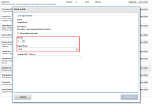
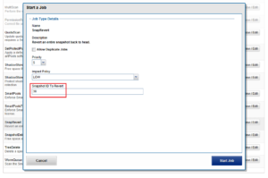
The recommended procedure for Smartfailing a node is as follows. In this example, we’ll assume that node 4 is down:

  1. From the CLI of any node except node 4, run the following command to Smartfail out the node:
# isi devices node smartfail --node-lnn 4
  1. Verify that node is removed from the cluster.
# isi status –q

(An ‘—S-’ will appear in node 4’s ‘Health’ column to indicate it has been Smartfailed).

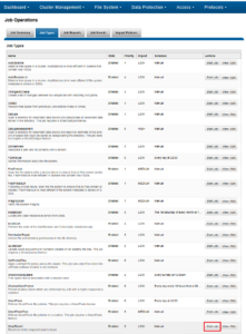
  1. Monitor the successful completion of the job engine’s MultiScan, FlexProtect/FlexProtectLIN jobs:
# isi job status
  1. Un-cable and remove the node from the rack for disposal

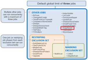
As mentioned above, there are two primary Job Engine jobs that run as a result of a Smartfail:

  • MultiScan
  • FlexProtect or FlexProtectLIN

MultiScan performs the work of the both AutoBalance and Collect jobs simultaneously, and it is triggered after every group change. The reason is that new file layouts and file deletions that happen during a disruption to the cluster may be imperfectly balanced or, in the case of deletions, simply lost.

The Collect job reclaims free space from previously unavailable nodes or drives. A mark and sweep garbage collector, it identifies everything valid on the filesystem in the first phase, then in the second phase scans the drives freeing anything that isn’t marked valid.

AutoBalance ensures that, when node and drive usage across the cluster are out of balance. This job scans through all the drives looking for files to re-layout to make use of the less filled devices.

The purpose of the FlexProtect job is to scan the file system after a device failure to ensure that all files remain protected. Incomplete protection levels are fixed, in addition to missing data or parity blocks caused by drive or node failures. This job is started automatically after Smartfailing a drive or node. If a Smartfailed device was the reason the job started, the device is marked gone (completely removed from the cluster) at the end of the job.

Although a new node can be added to a cluster at any time, it’s best to avoid major group changes during a Smartfail operation. This helps avoid any unnecessary interruptions of a critical job engine data reprotection job. However, since a node is down, there is a window of risk while the cluster is rebuilding the data from that cluster.  Under pressing circumstances the Smartfail operation can be paused, the node added, and then Smartfail resumed once the new node has happily joined the cluster.

Be aware that, if the node you are adding is the same node that was Smartfailed, the cluster maintains a record of that node and may prevent the re-introduction of that node until the Smartfail is complete.  To mitigate risk, Dell Technical Support should definitely be involved to ensure data integrity.

The time for a Smartfail to complete is hard to predict with any accuracy, and is dependent on:

Attribute Description
OneFS release Determines OneFS job engine version and how efficiently it operates.
System hardware Drive types, CPU, RAM, etc.
File system Quantity and type of data (ie. small vs large files), protection, tunables, etc.
Cluster load Processor and CPU utilization, capacity utilization, etc.

Typical Smartfail runtimes range from minutes for fairly empty, idle nodes with SSD and SAS drives to days for nodes with large SATA drives and a high capacity utilization. The FlexProtect job already runs at the highest job engine priority (value=1) and medium impact by default. As such, there isn’t much that can be done to speed up this job, beyond reducing cluster load.

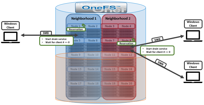
Smartfail is also a valuable tool for proactive cluster node replacement, for example during a hardware refresh.  Provided cluster quorum is not broken, a Smartfail can be initiated on multiple nodes concurrently – but never more than n/2 – 1 nodes (rounded up)!

If replacing an entire node-pool as part of a tech refresh, a SmartPools filepool policy can be crafted to migrate the data to another nodepool across the back-end network. When complete, the nodes can then be Smartfailed out, which should progress swiftly since they are now empty.

If multiple nodes are Smartfailed simultaneously, at the final stage of the process the node remove is serialized with around 60 seconds pause between each. The Smartfail job places the selected nodes in read-only mode while it copies the protection stripes to the cluster’s free space. Using SmartPools to evacuate data from a node or set of nodes in preparation to remove them is generally a good idea, and is usually a relatively fast process.

SmartPools’ Virtual Hot Spare (VHS) functionality helps ensure that node pools maintain enough free space to successfully re-protect data in the event of a Smartfail. Though configured globally, VHS actually operates at the node pool level so that nodes with different size drives reserve the appropriate VHS space. This helps ensures that, while data may move from one disk pool to another during repair, it remains on the same class of storage. VHS reservations are cluster wide and configurable as either a percentage of total storage (0-20%) or as a number of virtual drives (1-4), with the default being 10%.

Note, a Smartfail is not guaranteed to remove all data on a node. Any pool in a cluster that’s flagged with the ‘System’ flag can store /ifs/.ifsvar data. A filepool policy to move the regular data won’t address this data. Also, since SmartPools ‘spillover’ may have occurred at some point, there are no guarantees that an ‘empty’ node is completely devoid of data. For this reason, OneFS still has to search the tree for files that may have blocks residing on the node.

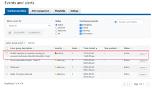
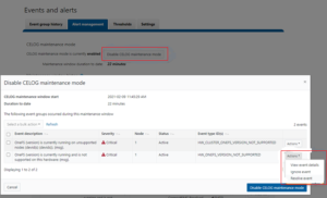
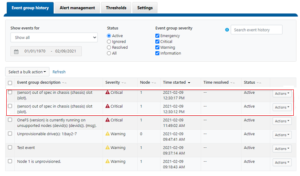
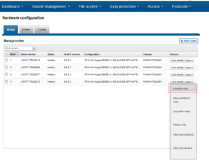
Nodes can be easily Smartfailed via the OneFS WebUI by navigating to Cluster Management > Hardware Configuration and selecting ‘Actions > More > Smartfail Node’ for the desired node(s):

Similarly, the following CLI commands initiate and halt the node Smartfail process respectively. Firstly, the ‘isi devices node smartfail’ command kicks off the Smartfail process on a node and removes it from the cluster.

# isi devices node smartfail -h

Syntax

# isi devices node smartfail

[--node-lnn <integer>]

[--force | -f]

[--verbose | -v]

If necessary, the ‘isi devices node stopfail’ command can be used to discontinue the Smartfail process on a node.

# isi devices node stopfail -h

Syntax

isi devices node stopfail

[--node-lnn <integer>]

[--force | -f]

[--verbose | -v]

Similarly, individual drives within a node can be Smartfailed with the ‘isi devices drive smartfail’ CLI command.

# isi devices drive smartfail { <bay> | --lnum <integer> | --sled <string> }

        [--node-lnn <integer>]

        [{--force | -f}]

        [{--verbose | -v}]

        [{--help | -h}]

When it comes to Smartfailing PowerScale chassis-based nodes, there are a couple of other things to be aware of regarding the mirrored journal:

  • When you smartfail a node in a node pair, you do not have to smartfail its partner node.
  • A node will still run indefinitely with its partner missing. However, this significantly increases the window of risk since there’s no journal mirror to rely on (in addition to lack of redundant power supply, etc).
  • If you do smartfail a single node in a pair, the journal is still protected by the vault and powerfail memory persistence.

OneFS Drain-based Upgrade

In the previous blog article, we looked at the mechanism by which OneFS enables non-disruptive upgrades. For NFS users, rolling node upgrades is typically a pretty seamless event since client connections can be dynamically moved and rebalanced across the other nodes. However, for SMB clients, rolling upgrades can be more impactful.

During an upgrade workflow, nodes will reboot, and the SMB protocol service must be stopped temporarily. This results in a brief disruption for Windows clients  connected to the rebooting node. To solve this, OneFS 9.2 introduces a drain-based upgrade feature, which provides a mechanism by which nodes are prevented from rebooting or restarting protocol services until all SMB clients have disconnected from the node. A single SMB client that does not disconnect can cause the upgrade to be delayed indefinitely, so the cluster administrator is provided with options to reboot the node despite persisting clients.

The drain-based upgrade supports both OneFS, firmware and combined upgrades, and can be configured and managed via the OneFS WebUI, CLI, and RESTful platform API.

  • SMB protocol
  • OneFS upgrades
  • Firmware upgrades
  • Cluster reboots
  • Combined upgrades (OneFS and Firmware)

Drain-based upgrade is predicated upon the parallel upgrade workflow, covered in a previous article, and which offers accelerated upgrades for large clusters by working across OneFS neighborhoods, or fault domains. By concurrently upgrading a node per neighborhood, the more node neighborhoods there are within a cluster the more parallel activity can occur.

For simplicities sake, assume a PowerScale cluster comprising five H700 chassis, divided into two neighborhoods, each containing ten nodes.

The following CLI command can be used to identify the correlation between the cluster’s nodes and OneFS neighborhoods, or failure domains:

# sysctl efs.lin.lock.initiator.coordinator_weights

Once the drain-based upgrade is started, a maximum of one node from each neighborhood will get the reservation which allows the nodes to upgrade simultaneously. OneFS will not reboot these nodes until the number of SMB clients is “0”. In this example Node 1 and Node 8 get the reservation for upgrading at the same time. However, there is one SMB connection to Node 1 and two SMB connections to Node 8. Neither of these nodes will be able to reboot until their SMB connection count gets to “0”. At this point, there are three options available:

Drain Action Description
Wait Wait until the SMB connection count reaches “0” or it hits the drain timeout value. The drain timeout value isa configurable parameter for each upgrade process. It is the maximum waiting period. If drain timeout is set to “0”, it means wait forever.
Delay drain Add the node into the delay list to delay client draining. The upgrade process will continue on another node in this neighborhood. After all the non-delayed nodes are upgraded, OneFS will rewind to the node in the delay list.
Skip drain Stop waiting for clients to migrate away from the draining node and reboot immediately.


The following CLI command can be used to confirm whether there are any active SMB connections. In this case, node 1 has one connected Windows client:

# isi statistics query current --keys=node.clientstats.connected.smb

 Node  node.clientstats.connected.smb

-------------------------------------

    1                               1

-------------------------------------

The ‘isi upgrade’ CLI command syntax can be used to perform the drain-based upgrade, and now includes flags for configuring drain-timeout and alert-timeout. In this example setting each to value 60 minutes and 45 minutes respectively. As such, if there is still an SMB connection after 45 minutes, a CELOG alert will be triggered to notify the cluster administrator. And after an hour, any remaining SMB connections will be dropped and the node upgrade reboot will continue.

# isi upgrade start --parallel --skip-optional --install-image-path=/ifs /data/<installation-file-name> --drain-timeout=60m --alert-timeout=45m

From the OneFS WebUI, the same can be achieved by navigating to Upgrade under Cluster management. In the example below, the WebUI indicates that node 1 is waiting for a draining SMB client. The response can be either to Skip or Delay.

If ‘Delay’ is selected, node one pauses to allow the remaining active client connection to drain:

After ‘Skip’ is chosen, the active client count is reduced to 0 and upgrade continues:

Here, the WebUI reports that node 2 has completed upgraded and is in the process of rebooting:

Once all nodes have completed, the upgrade can be committed by running the following command:

# isi upgrade cluster commit

Or from the WebUI:

Finally, confirm that the current version of OneFS is correct by running the following command:

# isi version

OneFS Non-disruptive Upgrades

When it comes to updating the OneFS version on a cluster, there are three primary options:

Of these, the simultaneous reboot is fast but disruptive, in that all the cluster’s nodes are upgraded and restarted in unison.

The other two options, rolling and parallel, are non-disruptive upgrades (NDUs), which allow a storage admin to upgrade a cluster while their end users continue to access data.

During the rolling upgrade process, one node at a time is updated to the new code, and the active clients attached to it are automatically migrated to other nodes in the cluster. Partial upgrade is also permitted, whereby a subset of cluster nodes can be upgraded, and the subset of nodes may also be grown during the upgrade. OneFS also allows an upgrade to be paused and resumed enabling customers to span upgrades over multiple smaller Maintenance Windows.

However, for larger clusters, OneFS also offers a parallel upgrade option. Parallel upgrade provides upgrade efficiency within node pools on clusters with multiple neighborhoods (availability zones), allowing the simultaneous upgrading of a node per neighborhood until the pool is complete . By doing this, the upgrade duration is dramatically reduced, while ensuring that end-users still continue to have full access to their data.

The parallel upgrade option avoids rebooting nodes unless a Diskpools DB reservation can be taken on that node. Each node runs the pre-upgrade optional and mandatory steps in lockstep. Nodes will not proceed to the MarkUpgrading state until the pre-upgrade checks have run successfully on all nodes. Once a node has reached the MarkUpgrading state, it will proceed through the upgrade hooks without regard for the completion state of hook on other nodes (ie not in lockstep).

Given that OneFS’ parallel upgrade option can dramatically improve the OneFS upgrade efficiency without impacting the data availability, the following formula can be used to estimate the duration of the parallel upgrade:

𝐸𝑠𝑡𝑖𝑚𝑎𝑡𝑖𝑜𝑛 𝑡𝑖𝑚𝑒 = (𝑝𝑒𝑟 𝑛𝑜𝑑𝑒 𝑢𝑝𝑔𝑟𝑎𝑑𝑒 𝑑𝑢𝑟𝑎𝑡𝑖𝑜𝑛) × (ℎ𝑖𝑔ℎ𝑒𝑠𝑡 𝑛𝑢𝑚𝑏𝑒𝑟 𝑜𝑓 𝑛𝑜𝑑𝑒𝑠 𝑝𝑒𝑟 𝑛𝑒𝑖𝑔ℎ𝑏𝑜𝑟ℎ𝑜𝑜𝑑)

In the above formula:

  • The first parameter – per node upgrade duration – is around 20 minutes on average.
  • The second parameter – the highest number of nodes per neighborhood – can be obtained by running the following CLI command:
# sysctl efs.lin.lock.initiator.coordinator_weights

For example, consider a 150 node OneFS cluster. In an ideal layout, there would be 15 neighborhoods, each containing ten nodes. Neighborhood 1 would comprise nodes 1 to 10, neighborhood 2, nodes 11 to 20, and so on and so forth.

During the parallel upgrade, the upgrade framework will pick at most one node from each neighborhood, to run the upgrading job simultaneously. So in this case, node 1 from neighborhood 1st, node 11 from neighborhood 2nd, node 21 from neighborhood 3rd and etc will be upgraded at the same time. Considering, they are all in different neighborhoods or failure domain, it will not impact the current running workload.  After the first pass completes, it will go to the 2nd pass and then 3rd and etc.

So, in the 150 node example above, the estimated duration of the parallel upgrade is 200 minutes:

𝐸𝑠𝑡𝑖𝑚𝑎𝑡𝑖𝑜𝑛 𝑡𝑖𝑚𝑒 = (𝑝𝑒𝑟 𝑛𝑜𝑑𝑒 𝑢𝑝𝑔𝑟𝑎𝑑𝑒 𝑑𝑢𝑟𝑎𝑡𝑖𝑜𝑛) × (ℎ𝑖𝑔ℎ𝑒𝑠𝑡 𝑛𝑢𝑚𝑏𝑒𝑟 𝑜𝑓 𝑛𝑜𝑑𝑒𝑠 𝑝𝑒𝑟 𝑛𝑒𝑖𝑔ℎ𝑏𝑜𝑟ℎ𝑜𝑜𝑑) = 20 × 10 = 200 𝑚𝑖𝑛𝑢𝑡𝑒𝑠

Under the hood, the OneFS non-disruptive upgrade system consists an UpgradeAgent and UpgradeSupervisor components.

The UpgradeAgent is a daemon that runs on every node. The UpgradeAgent’s role is to continually attempt to advance the upgrade process through to completion. It accomplishes this doing two things:

  1. Ensuring that an UpgradeSupervisoris running somewhere on the cluster by (a) checking to see if an upgrade is in progress and (b) waiting for its time slot, grabbing a lock file and then attempting to launch a supervisor.
  2. Receiving messages from any actively running UpgradeSupervisorand taking action on those messages.

The UpgradeSupervisor is a short-lived process which assesses the current state of the cluster and then takes action to advance the progress of the upgrade. The UpgradeSupervisor is stateless. It collects the persistent state of each node from that node’s UpgradeAgent using a status message. It also collects any information persistent on a cluster-wide basis. After reconstructing the current state of the upgrade process, it will then take action to affect the progress of the upgrade by dispatching an action message to the appropriate UpgradeAgent.

Since isi upgrade is an asynchronous process, the nodes in the cluster take turns running the controlling process. As such, the process that starts the upgrade does not run the upgrade but only sets it up. So when an ‘isi upgrade’ CLI command is run it will return fairly quickly. This also means that can’t stop the upgrade by stopping one process. Instead, a stop and restart option is provided using the ‘isi upgrade pause’ and ‘isi upgrade resume’ CLI commands.

Parallel upgrades are easily configured from the OneFS CLI by navigating to Cluster Management > Upgrade, and selecting ‘Parallel upgrade’ from the Upgrade type drop-down menu:

This can also be kicked-off from the OneFS command line using the following CLI syntax:

# isi upgrade start --parallel <upgrade_image>

Similarly, to start a rolling upgrade, which is the default, run:

# isi upgrade cluster start <upgrade_image>

The following CLI syntax will initiate a simultaneous upgrade:

# isi upgrade cluster start --simultaneous <upgrade_image>

Note that the upgrade framework always defaults to a rolling upgrade. Caution is advised when using the CLI to perform a simultaneous upgrade and the scheduling ‘type’ must be specified, i.e., –rolling, –simultaneous or –parallel

For example:

# isi upgrade cluster start /ifs/install.tar isi upgrade cluster start <code_path>

Since OneFS supports the ability to roll back to the previous version, in-order to complete an upgrade it must be committed.

isi upgrade cluster commit

Up until the time an upgrade is committed, an upgrade can be rolled back to the prior version as follows.

isi upgrade cluster rollback

The isi upgrade view CLI command can be used to monitor how the upgrade is progressing:

# isi upgrade viewisi upgrade view -i/--interactive

The following command will provide more detailed/verbose output:

# isi_upgrade_status

A faster, simpler version of isi_upgrade_status is also available:

# isi_upgrade_node_state-a (aggregate the latest hook update for each node)-devid=<X,Y,E-F>  (filter and display by devid)-lnn=<X-Y,A,C> (filter and display by LNN)-ts (time sort entries)

If the end of a maintenance window is reached but the cluster is not fully upgraded, the upgrade process can be quiesced and then restarted using the following CLI commands:

# isi upgrade pause
# isi upgrade resume

For example:

# isi upgrade pause

You are about to pause the running process, are you sure?  (yes/[no]):

yes

The process will be paused once the current step completes.

The current operation can be resumed with the command:

# isi upgrade resume

Note that pausing is not immediate: The upgrade will remain in a “Pausing” state until the currently
upgrading node is completed. Additional nodes will not be upgraded until the upgrade process is resumed.

The ‘pausing’ state can be viewed with the following commands: ‘isi upgrade view’ and ‘isi_upgrade_status’. Note that a rollback can be initiated either during ‘Pausing’ or ‘Paused’ states. Also, be aware that the ‘isi upgrade pause’ command has no effect when performing a simultaneous OneFS upgrade.

A rolling reboot can be initiated from the CLI on a subset of cluster nodes using the ‘isi upgrade rolling-reboot’ syntax and the ‘–nodes’ flag specifying the desired LNNs for upgrade:

# isi upgrade rolling-reboot --help

Description:

    Perform a Rolling Reboot of cluster.

Required Privileges:

    ISI_PRIV_SYS_UPGRADE

Usage:

    isi upgrade cluster rolling-reboot

        [--nodes <integer_range_list>]

        [--force]

        [{--help | -h}]

Options:

    --nodes <integer_range_list>

        List of comma (1,3,7) or dash (1-7) specified node LNNs to select. "all"

        can also be used to select all the cluster nodes at any given time.

  Display Options:

    --force

        Do not ask confirmation.

    --help | -h

        Display help for this command.

This ‘isi upgrade view’ syntax provides better visibility, status and progress of the rolling reboot process. For example:

# isi upgrade view

Upgrade Status:

Current Upgrade Activity: RollingReboot

   Cluster Upgrade State: committed

   Upgrade Process State: Not started

      Current OS Version: 9.2.0.0

      Upgrade OS Version: N/A

        Percent Complete: 0%

Nodes Progress:

     Total Cluster Nodes: 3

       Nodes On Older OS: 3

          Nodes Upgraded: 0

Nodes Transitioning/Down: 0

LNN  Progress  Version  Status

---------------------------------

1    100%        9.2.0.0  committed

2    rebooting   Unknown  non-responsive

3    0%          9.2.0.0  committed

Due to the duration of OneFS upgrades on larger clusters, it can sometimes be unclear if an OS upgrade is actually progressing or has stalled. To address this, if an upgrade is not making progress after fifteen minutes, the upgrade framework automatically sends a SW_UPGRADE_NODE_NON_RESPONSIVE alert via CELOG. For example:

# isi event events list

ID        Occurred       Sev    Lnn   Eventgroup ID  Message                                                                     

---------------------------------------------------------------------------------------------------------------

2.1805  06/14 04:33  C       2      1087               Excessive Time executing a Hook on Node: 3
# isi status

...

Critical Events:

Time                 LNN  Event                          

---------------     ----  ------------------------------ 

06/14 05:16:30  2    Excessive Time executing a ... 

...

The isi_upgrade_logs command also provides detailed upgrade tracking and debugging data.

Usage: isi_upgrade_logs [-a|--assessment][--lnn][--process {process name}][--level {start level,end level][--time {start time,end time][--guid {guid} | --devid {devid}]

 + No parameter this utility will pull error logs for the current upgrade process

 + -a or --assessment - will interrogate the last upgrade assessment run and display the results

The following arguments enable filtering to help extract the desired upgrade information:

Filter CMD Flag Description
–guid dump the logs for the node with the supplied guid
–devid dump the logs for the node/s with the supplied devid/s
–lnn dump the logs for the node/s with the supplied lnn/s
–process dump the logs for the node with the supplied process name
–level dump the logs for the supplied level range
–time dump the logs for the supplied time range
–metadata dump the logs matching the supplied regex

For example, to display all of the logs generated by isi_upgrade_agent_d on the node with LNN1:

# isi_upgrade_logs --lnn 1 --process /usr/sbin/isi_upgrade_agent_d  
…
1  2021-06-14T18:06:15  /usr/sbin/isi_upgrade_agent_d  Debug  Starting /usr/share/upgrade/event-actions/pre-upgrade-optional/read_only_node_check.py

1  2021-06-14T23:59:59  /usr/sbin/isi_upgrade_agent_d  Debug  Starting /usr/share/upgrade/event-actions/pre-upgrade-optional/isi_upgrade_checker

1  2021-06-14T18:06:15  /usr/sbin/isi_upgrade_agent_d  Debug  Starting /usr/share/upgrade/event-actions/pre-upgrade-optional/volcopy_check

1  2021-06-14T18:06:15  /usr/sbin/isi_upgrade_agent_d  Debug  Starting /usr/share/upgrade/event-actions/pre-upgrade-optional/empty

1  2021-06-14T18:06:15  /usr/sbin/isi_upgrade_agent_d  Debug  Starting Hook [/usr/share/upgrade/event-actions/pre-upgrade-optional/read_only_node_check.py]
 …

Note that the ‘–process’ flag requires the full name including path to be specified, as it is displayed in the logs.

For example, the following CLI syntax displays a list all of the Upgrade-related process names that have logged to LNN 1:

# isi_upgrade_logs --lnn 1 | awk ‘{print $3}’ | sort | uniq

These process names can then be added to the ‘–process’ argument.

OneFS CELOG Alerts and Events WebUI

The OneFS 9.2 release introduced a number of OneFS usability enhancements for managing cluster events and alerts. This new functionality makes it considerably simpler to filter events chronologically, categorize by their status, filter by the severity, search the event history, resolve, suppress or ignore bulk events, and manage scheduled maintenance windows.

For example, you can easily categorize, identify, and filter events by using the following criteria:

Action Detail
Show ·         Show events for:

–    Today

–    This week

–    This month

–    Custom range/

–    All

Categorize ·         Categorize events by their status:

–    Active

–    Ignored

–    Resolved

–    All

Filter ·         Filter events by severity:

–    Emergency

–    Critical

–    Warning

–    Information

Search ·         Search for specific event(s) in the event history
Resolve ·         Resolve bulk events
Ignore ·         Ignore bulk events

The new WebUI page for event group history can be accessed by navigating to Cluster management > Events and Alerts. For example:

With OneFS 9.2, CELOG maintenance mode can also easily be manually enabled and disabled. During a maintenance window, the system will continue to log events but not generate alerts. However, all events that occurred during the maintenance window can then be reviewed upon disabling maintenance mode. Active event groups will automatically resume generating alerts when the scheduled maintenance period ends. For example, to enable CELOG maintenance mode, in the OneFS WebUI select Cluster Management > Events and Alerts > Alert management tab and click on the ‘Enable CELOG maintenance mode’ button. In the prompt window, select ‘Enable CELOG maintenance mode’ as follows:

Create an Alert channel. Either SMTP or SNMP can be configured for the alert channel communication, and can be created by selecting ‘Create channel’:

To create an alert rule, click the tab Alerting rule and then click the button Create alert rule. In the prompt window, fill the Rule name, set the Rule condition to NEW, apply it to all the Alert categories, and attached it to the channel you have just created.

Events can be created using CLI syntax similar to the following:

# /usr/bin/isi_celog/celog_send_events.py -o 940100002

Heap looptimes: [-1]

running -1 [940100002]

1612871342 :: Sending eventids [940100002] with specifier None

940100002 message is OneFS {version} is currently running on unsupported nodes (devid(s) {devids}). {msg}.

1.195 (70368744177859) corresponds to eventid 940100002

Out of events to run. Exiting.
# /usr/bin/isi_celog/celog_send_events.py -o 940100001

Heap looptimes: [-1]

running -1 [940100001]

1612872343 :: Sending eventids [940100001] with specifier None

940100001 message is OneFS {version} is currently running and is not supported on this hardware: {msg}.

1.196 (70368744177860) corresponds to eventid 940100001

Out of events to run. Exiting.

During maintenance mode, OneFS will still show the event but there will be no associated alert. In this example, there is no SMTP alert email triggered.

The following CLI syntax can also be used to filter all the events which happened while the cluster was in CELOG maintenance mode:

# isi event groups list --maintenance-mode=true

ID   Started     Ended       Causes Short                           Lnn  Events  Severity

------------------------------------------------------------------------------------------

16   02/09 11:49 --          HW_CLUSTER_ONEFS_VERSION_NOT_SUPPORTED 1    1       critical

17   02/09 12:05 02/09 12:19 HW_ONEFS_VERSION_NOT_SUPPORTED         1    1       critical

------------------------------------------------------------------------------------------

Click the “Disable CELOG maintenance mode’ button. and select one of the following from the display window:

    1. View event details
    2. Ignore event
    3. Resolve event

In this example, the event HW_ONEFS_VERSION_NOT_SUPPORTED is marked resolved by clicking Action and Resolve event.

After the CELOG maintenance mode is disabled, you will get the email notification only for HW_CLUSTER_ONEFS_VERSION_NOT_SUPPORTED. The event which has been marked resolved will not trigger any notification.

When an event type is suppressed, it prevents an event from alerting on all configured CELOG channels. However, the event will still be displayed in the event group history.

To suppress an event type, click the button Suppress for a specific event under Event type ID tab. In this example, both 930100006 and 930100005 have been suppressed.

Create several events, for example by using CLI commands such as the following:

# /usr/bin/isi_celog/celog_send_events.py -o 930100006

Heap looptimes: [-1]

running -1 [930100006]

1612873812 :: Sending eventids [930100006] with specifier None

930100006 message is {sensor} out of spec in chassis {chassis} slot {slot}.

1.200 (70368744177864) corresponds to eventid 930100006

Out of events to run. Exiting.
# /usr/bin/isi_celog/celog_send_events.py -o 930100005

Heap looptimes: [-1]

running -1 [930100005]

1612873817 :: Sending eventids [930100005] with specifier None

930100005 message is {sensor} out of spec in chassis {chassis} slot {slot}.

1.201 (70368744177865) corresponds to eventid 930100005

Out of events to run. Exiting.

To list all the events in the suppressed list, use the following CLI syntax:

# isi event suppress list

ID        Name

—————————-

930100005 HWMON_ANY_DISCRETE

930100006 HWMON_ANY_METERS

—————————-

These suppressed events will only show in the event history and will not trigger any notification in any channels.

The desired event types can be un-suppressed by clicking pertinent the Un-suppress button(s).


OneFS External Key Management for Data Encryption

Data-at-rest data is inactive content that is physically housed on a cluster, or other storage medium. Protecting this data with cryptography ensures that it’s guarded against theft, in the event that drives or nodes are removed from a PowerScale cluster. Data-at-rest encryption (DARE) is a requirement for federal and industry regulations ensuring data is encrypted when it is stored. OneFS has provided DARE solutions for many years through self-encrypting drives (SEDs) and, until now, an internal key management system.

The new OneFS 9.2 release introduces External Key Management (EKM) support for encrypted clusters, through the key management interoperability protocol, or KMIP. This enables offloading of the Master Key from a node to an External Key Manager, such as SKLM, SafeNet or Vormetric. Enhanced security is inherently provided through the separation of key manager from cluster, since node(s) cannot be rebooted without the keys. It also supports the secure transport of nodes. Additionally, centralized key management is also made available for multiple SED clusters, and provides the option to migrate existing keys from a cluster’s internal key store.

EKM provides enhanced security through the separation of the key manager from the cluster, enabling the secure transport of nodes, and helping organizations to meet regulatory compliance and corporate data at rest security requirements.

In order to use the OneFS 9.2 External Key Manager feature, clearly a cluster with self-encrypting drives is needed. Additionally, for the SED drives to be unlocked and user data made available, each node in the cluster must first contact the KMIP server to obtain the master encryption key from the server. Nodes in the cluster cannot boot without contacting the KMIP server first. Note that clusters without all their nodes connected to a front-end network (NANON) do not support External Key Management.

For the server, a KMIP Compliant Server supporting KMIP version 1.2 or greater is needed, such as:

Vendor Key Manager & Version
Dell EMC CloudLink Center 6.0
Gemalto Gemalto KeySecure 8.7 k150v

Gemalto KeySecure 8.7 k170v

IBM Secure Key Lifecycle Manager (SKLM) 2.6.0.2

Secure Key Lifecycle Manager (SKLM) 2.7.0.0

Secure Key Lifecycle Manager (SKLM) 3.0.0

Thales E-Security KeyAuthority 4.0

Also:

  • KMIP Storage Array with SEDS Profile Version 1.0
  • KMIP server host/port information
  • 509 PKI for TLS mutual authentication
    • Certificate authority bundle
    • Client certificate and private key

External Key Management can be configured on OneFS 9.2 as follows:

  1. Obtain the KMIPs Server and Client Certificates. Copy both certificates to the cluster and make a note of the file names and location.
  2. From the OneFS web interface, select Access > Key Management

Alternatively, this can also be accomplished via the OneFS CLI:

# isi keymanager kmip servers create
  1. From the WebUI Key Management page, enter the KMIP server information and specify the filename with the server/client certificates’ location. If the KMIP has a client certificate password specified, enter that here. Check the “Enable Key Management” box and click Submit.

  1. Next, OneFS contacts the KMIP and confirms the connection or displays any errors.
  2. Once the KMIP server is added, the keys can now be migrated. Click the Keys tab to display all current Master Keys on the cluster. Click on Migrate all to migrate the keys to the KMIP server. From the “Migrate all” pop-up, click Migrate to start the migration.

  1. The key migration process may take several minutes or more to complete depending on the cluster and network utilization. During this time, a “Migration in process” message is displayed.

  1. Once the process is complete, and “Migration Successful” message is displayed:

The following OneFS key management CLI commands are also available:

To configure external KMIP servers:

# isi keymanager kmip servers -h     

Description:

    Configure external KMIP servers.

Required Privileges:

    ISI_PRIV_KEY_MANAGER

Usage:

    isi keymanager kmip servers <action>

        [--timeout <integer>]

        [{--help | -h}]

Actions:

    create    Configure a new external KMIP server.

    delete    Delete a external KMIP server.

    modify    Modify a external KMIP server.

    list      View a list of configured external KMIP servers.

    view      View a single external KMIP server.

Options:

  Display Options:

    --timeout <integer>

        Number of seconds for a command timeout (specified as 'isi --timeout NNN <command>').

    --help | -h

        Display help for this command.

See 'isi keymanager kmip servers <subcommand> --help' for more information on a specific subcommand.

To manage SED keystore settings:

# isi keymanager sed settings -h

Description:

    Manage self-encrypting drive keystore settings.

Required Privileges:

    ISI_PRIV_KEY_MANAGER

Usage:

    isi keymanager sed settings <action>

        [{--help | -h}]

Actions:

    modify    Modify SED settings

    view      View current SED settings.

Options:

  Display Options:

    --help | -h

        Display help for this command.

See 'isi keymanager sed settings <subcommand> --help' for more information on a specific subcommand.

And to report keymanager SED status:

# isi keymanager sed status    

 Node Status  Location  Remote Key ID  Error Info(if any)
----------------------------------------------------------
  1   REMOTE  Server    F84B50640CABD44B9D5F75427C2B5E

  2   REMOTE  Server    24285969BD8804A9A61EE39D99573B

  3   REMOTE   Server    7D561B1CA89B72B891B21BF834097F  
-----------------------------------------------------------
Total: 3

OneFS Cluster Configuration Export & Import

OneFS 9.2 introduces the ability to export a cluster’s configuration, which can then be used to perform a configuration restore to the original cluster, or to an alternate cluster that also supports this feature. A configuration export and import can be performed via either the OneFS CLI or platform API, and encompasses the following OneFS components for configuration backup and restore:

  • NFS
  • SMB
  • S3
  • NDMP
  • HTTP
  • Quotas
  • Snapshots

The underlying architecture comprises four layers , and the process flow is as follows:

Each layer of the architecture is a follows:

 Component Description
User Interface Allows users to submit operations with multiple choices, such as REST, CLI, or WebUI.
pAPI Handler Performs different actions according to the requests flowing in
Config Manager Core layer executing different jobs which are called by PAPI handlers.
Database Lightweight database manage asynchronous jobs, tracing state and receiving task data.

By default, configuration backup and restore files reside at:

File Location
Backup JSON file: /ifs/data/Isilon_Support/config_mgr/backup/<JobID>/<component>_<JobID>.json
Restore JSON file: /ifs/data/Isilon_Support/config_mgr/restore/<JobID>/<component>_<JobID>.json

The log file for configuration manager is located at /var/log/config_mgr.log and can be useful to monitor the progress of a config backup and restore.

So let’s take a look at this cluster configuration management process:

The following procedure steps through the export and import of a cluster’s NFS and SMB configuration – within the same cluster:

  1. Open an SSH connection to any node in the cluster and log in using the root account.
  2. Create several SMB shares and NFS exports using the following CLI command
# isi smb shares create --create-path --name=test --path=/ifs/test

# isi smb shares create --create-path --name=test2 --path=/ifs/test2

# isi nfs exports create --paths=/ifs/test

# isi nfs exports create --paths=/ifs/test2
  1. Export the NFS and SMB configuration using the following CLI command
# isi cluster config exports create --components=nfs,smb --verbose

As indicated in the output below, the job ID for this export task is ‘ PScale-20210524105345’

Are you sure you want to export cluster configuration? (yes/[no]): yes

This may take a few seconds, please wait a moment

Created export task ' PScale-20210524105345'
  1. To view the results of the export operation, use the following CLI command:
# isi cluster config exports view PScale-20210524105345

As displayed in the output below, the backup JSON files are located at /ifs/data/Isilon_Support/config_mgr/backup/PScale-20210524105345

     ID: PScale-20210524105345

 Status: Successful

   Done: ['nfs', 'smb']

 Failed: []

Pending: []

Message:

   Path: /ifs/data/Isilon_Support/config_mgr/backup/PScale-20210524105345
  1. The JSON files can be viewed under /ifs/data/Isilon_Support/config_mgr/backup/ PScale-20210524105345. OneFS will generate a separate configuration backup JSON file for each component (ie. SMB and NFS in this example):
# ls /ifs/data/Isilon_Support/config_mgr/backup/PScale-20210524105345 backup_readme.json              nfs_PScale-20210524105345.json  smb_PScale-20210524105345.json
  1. Delete all the SMB shares and NFS exports using the following commands:
# isi smb shares delete test

# isi smb shares delete test2

# isi nfs exports delete 9

# isi nfs exports delete 10
  1. Use the following CLI command to restore the SMB and NFS configuration:
# isi cluster config imports create PScale-20210524105345 --components=smb,nfs
  1. From the output below, the import job ID is ‘ PScale-20210524105345’
Are you sure you want to import cluster configuration? (yes/[no]): yes

This may take a few seconds, please wait a moment

Created import task ' PScale-20210524105345'
  1. To view the restore results, use the following command:
# isi cluster config imports view PScale-20210524105345

       ID: PScale-20210524110659

Export ID: PScale-20210524105345

   Status: Successful

     Done: ['nfs', 'smb']

   Failed: []

  Pending: []

  Message:

     Path: /ifs/data/Isilon_Support/config_mgr/restore/ PScale-20210524110659
  1. Verify that the SMB shares and NFS exports are restored:
# isi smb shares list

Share Name  Path

----------------------

test        /ifs/test

test2       /ifs/test2

----------------------

Total: 2
# isi nfs exports list

ID   Zone   Paths      Description

-----------------------------------

11   System /ifs/test

12   System /ifs/test2

-----------------------------------

Total: 2

A WebUI management component for this feature will be included in a future release, as will the ability to run a diff, or comparison, between two exported configurations .

PowerScale F900 All-flash NVMe Node

In this article, we’ll take a quick peek at the new PowerScale F900 hardware platform that was released last week. Here’s where this new node sits in the current PowerScale hardware hierarchy:

The PowerScale F900 is a high-end all-flash platform that utilizes NVMe SSDs and a dual-CPU 2U PowerEdge platform with 736GB of memory per node.  The ideal use cases for the F900 include high performance workflows, such as M&E, EDA, AI/ML, and other HPC applications and next gen workloads.

An F900 cluster can comprise between 3 and 252 nodes, each of which contains twenty four 2.5” drive bays populated with a choice of 1.92TB, 3.84TB, 7,68TB, or 15.36TB enterprise NVMe SSDs, and netting up to 181TB of RAM and 91PB of all-flash storage per cluster. Inline data reduction, which incorporates compression, dedupe, and single instancing, is also included as standard to further increase the effective capacity.

The F900 is based on the 2U Dell R740 PowerEdge server platform, with dual socket Intel CPUs, as follows:

Description PowerScale F900 

(PE R740xd platform w/ NVMe SSDs)

Minimum # of nodes in a cluster 3
Raw capacity per minimum sized cluster (3 nodes) 138TB to 1080TB

Drive capacity options:

1.92 TB, 3.82 TB, 7.68 TB, or 15.36 TB

SSD Drives in min. sized cluster 24 x 3 = 72
Rack Unit (RU) per min. cluster 6 RU
Processor Dual socket Intel Xeon Processor Gold 6240R (2.2GHz, 24C)
Memory per node 736 GB per node
Front-End Connectivity 2 x 10/25GbE or 2 x 40/100GbE
Back-end Connectivity 2 x 40/100GbE or

2 x QDR Infiniband (IB) for interoperability to previous generation clusters

Or, as reported by OneFS:

# isi_hw_status -ic
SerNo: 5FH9K93
Config: PowerScale F900
ChsSerN: 5FH9K93
ChsSlot: n/a
FamCode: F
ChsCode: 2U
GenCode: 00
PrfCode: 9
Tier: 7
Class: storage
Series: n/a
Product: F900-2U-Dual-736GB-2x100GE QSFP+-45TB SSD
HWGen: PSI
Chassis: POWEREDGE (Dell PowerEdge)
CPU: GenuineIntel (2.39GHz, stepping 0x00050657)
PROC: Dual-proc, 24-HT-core
RAM: 789523222528 Bytes
Mobo: 0YWR7D (PowerScale F900)
NVRam: NVDIMM (NVDIMM) (8192MB card) (size 8589934592B)
DskCtl: NONE (No disk controller) (0 ports)
DskExp: None (No disk expander)
PwrSupl: PS1 (type=AC, fw=00.1D.7D)
PwrSupl: PS2 (type=AC, fw=00.1D.7D)

The F900 nodes are available in two networking configurations, with either a 10/25GbE or 40/100GbE front-end, plus a standard 100GbE or QDR Infiniband back-end for each.

The 40G and 100G connections are actually four lanes of 10G and 25G respectively, allowing switches to ‘breakout’ a QSFP port into 4 SFP ports. While this is automatic on the Dell back-end switches, some front-end switches may need configuring.

Drive subsystem-wise, the PowerScale F900 has twenty four total drive bays spread across the front of the chassis:

Under the hood on the F900, OneFS provides support NVMe across PCIe lanes, and the SSDs use the NVMe and NVD drivers. The NVD is a block device driver that exposes an NVMe namespace like a drive and is what most OneFS operations act upon, and each NVMe drive has a /dev/nvmeX, /dev/nvmeXnsX and /dev/nvdX device entry  and the locations are displayed as ‘bays’. Details can be queried with OneFS CLI drive utilities such as ‘isi_radish’ and ‘isi_drivenum’. For example:

# isi devices drive list
Lnn Location Device Lnum State Serial
------------------------------------------------------
1 Bay 0 /dev/nvd15 9 HEALTHY S61DNE0N702037
1 Bay 1 /dev/nvd14 10 HEALTHY S61DNE0N702480
1 Bay 2 /dev/nvd13 11 HEALTHY S61DNE0N702474
1 Bay 3 /dev/nvd12 12 HEALTHY S61DNE0N702485
1 Bay 4 /dev/nvd19 5 HEALTHY S61DNE0N702031
1 Bay 5 /dev/nvd18 6 HEALTHY S61DNE0N702663
1 Bay 6 /dev/nvd17 7 HEALTHY S61DNE0N702726
1 Bay 7 /dev/nvd16 8 HEALTHY S61DNE0N702725
1 Bay 8 /dev/nvd23 1 HEALTHY S61DNE0N702718
1 Bay 9 /dev/nvd22 2 HEALTHY S61DNE0N702727
1 Bay 10 /dev/nvd21 3 HEALTHY S61DNE0N702460
1 Bay 11 /dev/nvd20 4 HEALTHY S61DNE0N700350
1 Bay 12 /dev/nvd3 21 HEALTHY S61DNE0N702023
1 Bay 13 /dev/nvd2 22 HEALTHY S61DNE0N702162
1 Bay 14 /dev/nvd1 23 HEALTHY S61DNE0N702157
1 Bay 15 /dev/nvd0 0 HEALTHY S61DNE0N702481
1 Bay 16 /dev/nvd7 17 HEALTHY S61DNE0N702029
1 Bay 17 /dev/nvd6 18 HEALTHY S61DNE0N702033
1 Bay 18 /dev/nvd5 19 HEALTHY S61DNE0N702478
1 Bay 19 /dev/nvd4 20 HEALTHY S61DNE0N702280
1 Bay 20 /dev/nvd11 13 HEALTHY S61DNE0N702166
1 Bay 21 /dev/nvd10 14 HEALTHY S61DNE0N702423
1 Bay 22 /dev/nvd9 15 HEALTHY S61DNE0N702483
1 Bay 23 /dev/nvd8 16 HEALTHY S61DNE0N702488
------------------------------------------------------
Total: 24

Or for the details of a particular drive:

# isi devices drive view 15
Lnn: 1
Location: Bay 15
Lnum: 0
Device: /dev/nvd0
Baynum: 15
Handle: 346
Serial: S61DNE0N702481
Model: Dell Ent NVMe AGN RI U.2 1.92TB
Tech: NVME
Media: SSD
Blocks: 3750748848
Logical Block Length: 512
Physical Block Length: 512
WWN: 363144304E7024810025384500000003
State: HEALTHY
Purpose: STORAGE
Purpose Description: A drive used for normal data storage operation
Present: Yes
Percent Formatted: 100
# isi_radish -a /dev/nvd0

Bay 15/nvd0   is Dell Ent NVMe AGN RI U.2 1.92TB FW:2.0.2 SN:S61DNE0N702481, 3750748848 blks

Log Sense data (Bay 15/nvd0  ) --

Supported log pages 0x1 0x2 0x3 0x4 0x5 0x6 0x80 0x81

SMART/Health Information Log

============================

Critical Warning State:         0x00

 Available spare:               0

 Temperature:                   0

 Device reliability:            0

 Read only:                     0

 Volatile memory backup:        0

Temperature:                    310 K, 36.85 C, 98.33 F

Available spare:                100

Available spare threshold:      10

Percentage used:                0

Data units (512,000 byte) read: 3804085

Data units written:             96294

Host read commands:             29427236

Host write commands:            480646

Controller busy time (minutes): 7

Power cycles:                   36

Power on hours:                 774

Unsafe shutdowns:               31

Media errors:                   0

No. error info log entries:     0

Warning Temp Composite Time:    0

Error Temp Composite Time:      0

Temperature Sensor 1:           310 K, 36.85 C, 98.33 F

Temperature 1 Transition Count: 0

Temperature 2 Transition Count: 0

Total Time For Temperature 1:   0

Total Time For Temperature 2:   0

SMART status is threshold NOT exceeded (Bay 15/nvd0  )

Error Information Log

=====================

No error entries found

The F900 nodes’ front panel has limited functionality compared to older platform generations and will simply allow the user to join a node to a cluster and display the node name after the node has successfully joined the cluster.

Similar to legacy Gen6 platforms, a PowerScale node’s serial number can be found either by viewing /etc/isilon_serial_number or running the ‘isi_hw_status | grep SerNo’ CLI command syntax. The serial number reported by OneFS will match that of the service tag attached to the physical hardware and the /etc/isilon_system_config file will report the appropriate node type. For example:

# cat /etc/isilon_system_config

PowerScale F900

OneFS 9.2 and PowerScale F900 Introduction

It’s release season here and we’re delighted to introduce both PowerScale OneFS 9.2 and the new PowerScale F900 all-flash NVMe node.

The PowerScale F900 will be the highest performing platform in the PowerScale portfolio. It’s based on the Dell R740xd platform, and features dual socked 24-core 2.2GHz Intel Xeon Gold CPU, 736 GB of RAM, 100Gb Ethernet or QDR Infiniband backend, and twenty four 2.5 inch NVMe drives per 2U node. These drives are available in 1.9TB, 3.8TB, 7.4TB and 15TB sizes, yielding 46TB, 92TB, 184TB, and 360TB raw node capacities respectively, allowing the F900 to deliver up to 93PB of raw NVMe all-flash capacity per cluster. ​

A recent Forrester Total Economic Indicator (TEI) study showed that the F900 can deliver an ROI of up to 374% and a payback period of less than 6 months. ​Plus it can be consumed either as an appliance or as an APEX Data Storage Service.

The F900 can scale from 3 to 252 nodes per cluster, and inline data reduction is enabled by default to further extend the effective capacity and efficiency of this platform.

With the latest OneFS 9.2, we have also powered up the F600 and F200, launched last year. There’s higher performance with up to 70% increase in sequential reads for F600 and up to 25% for sequential reads for the F200. Plus customers also get more flexibility through new drive options, and the ability to non-disruptively add these nodes to existing Isilon clusters. Finally, customers get data-at-rest encryption through self-encrypting drives (SED) on F200.

OneFS 9.2 also introduces Remote Direct Memory Access support for applications and clients with NFS over RDMA, and allows substantially higher throughput performance, especially for single connection and read intensive workloads such as M&E edit and playback and machine learning – while also reducing both cluster and client CPU utilization. It also provides a foundation for future OneFS interoperability with NVIDIA’s GPUDirect.

Specifically, OneFS 9.2 supports NFSv3 over RDMA by leveraging the ROCEv2 network protocol (also known as Routable RoCE or RRoCE). New OneFS CLI and WebUI configuration options have been added, including global enablement, and IP pool configuration, filtering and verification of RoCEv2 capable network interfaces. Be aware that neither ROCEv1 nor NFSv4 over RDMA are supported in the OneFS 9.2 release. And IPv6 is also unsupported when using NFSv3 over RDMA

NFS over RDMA is available on all PowerScale which contain Mellanox ConnectX network adapters on the front end with either 25, 40, or 100 Gig Ethernet connectivity. The ‘isi network interfaces list’ CLI command can be used to easily identify which of a cluster’s NICs support RDMA.

The new 9.2 release introduces External Key Management support for encrypted clusters, through the key management interoperability protocol, or KMIP, which enables offloading of the Master Key from a node to an External Key Manager, such as SKLM, SafeNet or Vormetric. This allows centralized key management for multiple SED clusters, and includes an option to migrate existing keys from a cluster’s internal key store.

This feature provides enhanced security through the separation of the key manager from the cluster, enabling the secure transport of nodes, and helping organizations to meet regulatory compliance and corporate data at rest security requirements

Configuration is via either the WebUI or CLI, and, in order to test the External Key Manager feature, a PowerScale cluster with self-encrypting drives will be required:

In addition to external key management for SEDs, OneFS 9.2 introduces several other Security & Compliance features, including Administrator-only Log Access, where Security and Federal requirements mandate limiting access to configuration and log information to administrators only for /ifsvar, /var/log, /boot, and a variety of /etc config files and subdirectories.

Also, in OneFS 9.2, the HTTP Basic Authentication scheme will be disabled by default, on new installs requiring session-based authentication. This only impacts the API and RAN endpoints of the web server, including /platform, /object, and /namespace on TCP port 8080. The regular HTTP protocol access on TCP 80 and 443 remains unchanged.

9.2 also introduces a new roles-based administration privilege, ISI_PRIV_RESTRICTED_AUTH, intended for help-desk admins that don’t require full ISI_PRIV_AUTH privileges. This means that an admin with ISI_PRIV_RESTRICTED_AUTH can only modify users and groups with the same or fewer privileges.

While IPv6 has been available in OneFS for several releases now, 9.2 introduces support to meet the stringent USGv6 security requirements for United States Government deployments. In particular, the USGv6 feature implements both Router Advertisements to update the IPv6 default gateway, and Duplicate Address Detection to detect conflicting IP addresses. SmartConnect DNS is also enhanced to detect DAD for the SmartConnect Service IP, allowing it to log and remove an SSIP if a duplicate is detected.

There are also several serviceability-related enhancements in this new release. As part of OneFS’ always-on initiative, 9.2 introduces Drain Based Upgrades, where nodes are prevented from rebooting or restarting protocol services until all SMB clients have disconnected from the node. Since a single SMB client that does not disconnect could cause the upgrade to be delayed indefinitely, options are available to reboot the node, despite persisting clients.

OneFS 9.2 sees a redesign of the CELOG WebUI for improved usability. This makes it simple to filter events chronologically, categorize by their status, filter by the severity, easily search the event history, resolve, suppress or ignore bulk events, and more easily manage scheduled maintenance windows.

9.2 also introduces the ability to export a cluster’s configuration, which can then be used to perform a config restore to either the original or a different cluster. This can be performed either from the CLI or platform API, and includes the configuration for the core protocols (NFS, SMB, S3 and HDFS) plus Snapshots, Quotas, and NDMP backup,

Another feature of OneFS 9.2 is S3 ETag Consistency. Unlike AWS, if the MD5 checksum is not specified in an S3 client request, OneFS generates a unique string for that file as an ETag in response, which can cause issues with some applications. Therefore, 9.2 now allows admins to specify if the MD5 should be calculated and verified.

In 9.2, Energy Star efficiency data is now retrieved through the IPMI interface, and reported via the CLI, allowing cluster admins and compliance engineers to query a cluster’s inlet temperatures and power consumption.

With OneFS 9.2, In-line data reduction is extended to include the new F900 platform. OneFS in-line data reduction substantially increases a cluster’s storage density, and helps eliminate management burden, while seamlessly boosting efficiency and lowering the TCO. The in-line data reduction write pipeline comprises three main phases:

  • Zero block removal
  • In-line dedupe
  • In-line compression

And, like everything OneFS, it scales linearly across a cluster, as additional nodes are added.

We’ll be looking more closely at these new features and functionality over the course of the next few blog articles.

OneFS SnapRevert Job

There have been a couple of recent inquiries from the field about the SnapRevert job.

For context, SnapRevert is one of three main methods for restoring data from a OneFS snapshot. The options are:

Method Description
Copy Copying specific files and directories directly from the snapshot
Clone Cloning a file from the snapshot
Revert Reverting the entire snapshot via the SnapRevert job

Copying a file from a snapshot duplicates that file, which roughly doubles the amount of storage space it consumes. Even if the original file is deleted from HEAD, the copy of that file will remain in the snapshot. Cloning a file from a snapshot also duplicates that file. Unlike a copy, however, a clone does not consume any additional space on the cluster – unless either the original file or clone is modified.

However, the most efficient of these approaches is the SnapRevert job, which automates the restoration of an entire snapshot to its top level directory. This allows for quickly reverting to a previous, known-good recovery point – for example in the event of virus outbreak. The SnapRevert job can be run from the Job Engine WebUI, and requires adding the desired snapshot ID.

There are two main components to SnapRevert:

  • The file system domain that the objects are put into.
  • The job that reverts everything back to what’s in a snapshot.

So what exactly is a SnapRevert domain? At a high level, a domain defines a set of behaviors for a collection of files under a specified directory tree. The SnapRevert domain is described as a ‘restricted writer’ domain, in OneFS parlance. Essentially, this is a piece of extra filesystem metadata and associated locking that prevents a domain’s files being written to while restoring a last known good snapshot.

Because the SnapRevert domain is essentially just a metadata attribute placed onto a file/directory, a best practice is to create the domain before there is data. This avoids having to wait for DomainMark (the aptly named job that marks a domain’s files) to walk the entire tree, setting that attribute on every file and directory within it.

The SnapRevert job itself actually uses a local SyncIQ policy to copy data out of the snapshot, discarding any changes to the original directory.  When the SnapRevert job completes, the original data is left in the directory tree.  In other words, after the job completes, the file system (HEAD) is exactly as it was at the point in time that the snapshot was taken.  The LINs for the files/directories don’t change, because what’s there is not a copy.

SnapRevert can be manually run from the OneFS WebUI by navigating to Cluster Management > Job Operations > Job Types > SnapRevert and clicking the ‘Start Job’ button.

Additionally, the job’s impact policy and relative priority can also be adjusted, if desired:

Before a snapshot is reverted, SnapshotIQ creates a point-in-time copy of the data that is being replaced. This enables the snapshot revert to be undone later, if necessary.

Additionally, individual files, rather than entire snapshots, can also be restored in place using the isi_file_revert command line utility.

# isi_file_revert
usage:
isi_file_revert -l lin -s snapid
isi_file_revert -p path -s snapid
-d (debug output)
-f (force, no confirmation)

This can help drastically simplify virtual machine management and recovery, for example.

Before creating snapshots, it’s worth considering that reverting a snapshot requires that a SnapRevert domain exist for the directory that is being restored. As such, it is recommended that you create SnapRevert domains for those directories while the directories are empty. Creating a domain for an empty (or sparsely populated) directory takes considerably less time.

Files may belong to multiple domains. Each file stores a set of domain IDs indicating which domain they belong to in their inode’s extended attributes table. Files inherit this set of domain IDs from their parent directories when they are created or moved. The domain IDs refer to domain settings themselves, which are stored in a separate system B-tree. These B-tree entries describe the type of the domain (flags), and various other attributes.

As mentioned, a Restricted-Write domain prevents writes to any files except by threads that are granted permission to do so. A SnapRevert domain that does not currently enforce Restricted-Write shows up as “(Writable)” in the CLI domain listing.

Occasionally, a domain will be marked as “(Incomplete)”. This means that the domain will not enforce its specified behavior. Domains created by job engine are incomplete if not all of the files that are part of the domain are marked as being members of that domain. Since each file contains a list of domains of which it is a member, that list must be kept up to date for each file. The domain is incomplete until each file’s domain list is correct.

In addition to SnapRevert, OneFS also currently uses domains for SyncIQ replication and SnapLock immutable archiving.

A SnapRevert domain needs to be created on a directory before it can be reverted to a particular point in time snapshot. As mentioned before, the recommendation is to create SnapRevert domains for a directory while the directory is empty.

The root path of the SnapRevert domain must be the same root path of the snapshot. For example, a domain with a root path of /ifs/data/marketing cannot be used to revert a snapshot with a root path of /ifs/data/marketing/archive.

For example, for snaphsot DailyBackup_04-27-2021_12:00 which is rooted at /ifs/data/marketing/archive:

  1. First, set the SnapRevert domain by running the DomainMark job (which marks all the files):
# isi job jobs start domainmark --root /ifs/data/marketing --dm-type SnapRevert
  1. Verify that the domain has been created:
# isi_classic domain list –l

In order to restore a directory back to the state it was in at the point in time when a snapshot was taken, you need to:

  • Create a SnapRevert domain for the directory.
  • Create a snapshot of a directory.

To accomplish this:

  1. First, identify the ID of the snapshot you want to revert by running the isi snapshot snapshots view command and picking your PIT (point in time).

For example:

# isi snapshot snapshots view DailyBackup_04-27-2021_12:00

ID: 38

Name: DailyBackup_04-27-2021_12:00

Path: /ifs/data/marketing

Has Locks: No

Schedule: daily

Alias: -

Created: 2021-04-27T12:00:05

Expires: 2021-08-26T12:00:00

Size: 0b

Shadow Bytes: 0b

% Reserve: 0.00%

% Filesystem: 0.00%

State: active
  1. Revert to a snapshot by running the isi job jobs start command. The following command reverts to snapshot ID 38 named DailyBackup_04-27-2021_12:00:
# isi job jobs start snaprevert --snapid 38

This can also be done from the WebUI, by navigating to Cluster Management > Job Operations > Job Types > SnapRevert and clicking the ‘Start Job’ button.

OneFS automatically creates a snapshot right before the SnapRevert process reverts the specified directory tree. The naming convention for these snapshots is of the form: <snapshot_name>.pre_revert.*

# isi snap snap list | grep pre_revert
39 DailyBackup_04-27-2021_12:00.pre_revert.1655328160 /ifs/data/marketing

This allows for an easy roll-back of a SnapRevert if the desired results are not achieved.

Note that, if a domain is currently preventing the modification or deletion of a file, a protection domain cannot be created on a
directory that contains that file. For example, if files under /ifs/data/smartlock are set to a WORM state by a
SmartLock domain, OneFS will not allow a SnapRevert domain to be created on /ifs/data/.

If desired or required, SnapRevert domains can also be deleted using the job engine CLI. For example, to delete the SnapRevert domain at /ifs/data/marketing:

# isi job jobs start domainmark --root /ifs/data/marketing --dm-type SnapRevert --delete

How To Configure NFS over RDMA

Starting from OneFS 9.2.0.0, NFSv3 over RDMA is introduced for better performance. Please refer to Chapter 6 of OneFS NFS white paper for the technical details. This article provides guidance on using the NFSv3 over RDMA feature with your OneFS clusters. Note that the OneFS NFSv3 over RDMA functionality requires that any clients are ROCEv2 capable. As such, client-side configuration is also needed.

OneFS Cluster configuration

To use NFSv3 over RDMA, your OneFS cluster hardware must meet requirements:

  • Node type: All Gen6 (F800/F810/H600/H500/H400/A200/A2000), F200, F600, F900
  • Front end network: Mellanox ConnectX-3 Pro, ConnectX-4 and ConnectX-5 network adapters that deliver 25/40/100 GigE speed.

1. Check your cluster network interfaces have ROCEv2 capability by running the following command and noting the interfaces that report ‘SUPPORTS_RDMA_RRoCE’. This check is only available on the CLI.

# isi network interfaces list -v

2. Create an IP pool that contains ROCEv2 capable network interface.

(CLI)

# isi network pools create --id=groupnet0.40g.40gpool1 --ifaces=1:40gige- 1,1:40gige-2,2:40gige-1,2:40gige-2,3:40gige-1,3:40gige-2,4:40gige-1,4:40gige-2 --ranges=172.16.200.129-172.16.200.136 --access-zone=System --nfsv3-rroce-only=true

(WebUI) Cluster management –> Network configuration

3. Enable NFSv3 over RDMA feature by running the following command.

(CLI)

# isi nfs settings global modify --nfsv3-enabled=true --nfsv3-rdma-enabled=true

(WebUI) Protocols –> UNIX sharing(NFS) –> Global settings

4. Enable OneFS cluster NFS service by running the following command.

(CLI)

# isi services nfs enable

(WebUI) See step 3

5. Create NFS export by running the following command. The –map-root-enabled=false is used to disable NFS export root-squash for testing purpose, which allows root user to access OneFS cluster data via NFS.

(CLI)

# isi nfs exports create --paths=/ifs/export_rdma --map-root-enabled=false

(WebUI) Protocols –> UNIX sharing (NFS) –> NFS exports

NFSv3 over RDMA client configuration

Note: As the client OS and Mellanox NICs may vary in your environment, you need to look for your client OS documentation and Mellanox documentation for the accurate and detailed configuration steps. This section only demonstrates an example configuration using our in-house lab equipment.

To use NFSv3 over RDMA service of OneFS cluster, your NFSv3 client hardware must meet requirements:

  • RoCEv2 capable NICs: Mellanox ConnectX-3 Pro, ConnectX-4, ConnectX-5, and ConnectX-6
  • NFS over RDMA Drivers: Mellanox OpenFabrics Enterprise Distribution for Linux (MLNX_OFED) or OS Distributed inbox driver. It is recommended to install Mellanox OFED driver to gain the best performance.

If you just want to have a functional test on the NFSv3 over RDMA feature, you can set up Soft-RoCE for your client.

Set up a RDMA capable client on physical machine

In the following steps, we are using the Dell PowerEdge R630 physical server with CentOS 7.9 and Mellanox ConnectX-3 Pro installed.

  1. Check OS version by running the following command:
# cat /etc/redhat-release

CentOS Linux release 7.9.2009 (Core)


2. Check the network adapter model and information. From the output, we can find the ConnectX-3 Pro is installed, and the network interfaces are named 40gig1 and 40gig2.

# lspci | egrep -i --color 'network|ethernet'

01:00.0 Ethernet controller: Intel Corporation 82599ES 10-Gigabit SFI/SFP+ Network Connection (rev 01)

01:00.1 Ethernet controller: Intel Corporation 82599ES 10-Gigabit SFI/SFP+ Network Connection (rev 01)

03:00.0 Ethernet controller: Mellanox Technologies MT27520 Family [ConnectX-3 Pro]

05:00.0 Ethernet controller: Intel Corporation I350 Gigabit Network Connection (rev 01)

05:00.1 Ethernet controller: Intel Corporation I350 Gigabit Network Connection (rev 01)

# lshw -class network -short

H/W path

==========================================================

/0/102/2/0&nbsp;&nbsp;&nbsp;&nbsp;&nbsp;&nbsp;&nbsp;&nbsp;&nbsp;&nbsp; 40gig1&nbsp;&nbsp;&nbsp;&nbsp; network&nbsp;&nbsp;&nbsp;&nbsp;&nbsp;&nbsp;&nbsp; MT27520 Family [ConnectX-3 Pro]

/0/102/3/0&nbsp;&nbsp;&nbsp;&nbsp;&nbsp;&nbsp;&nbsp;&nbsp;&nbsp;&nbsp;&nbsp;&nbsp;&nbsp;&nbsp;&nbsp;&nbsp;&nbsp;&nbsp;&nbsp;&nbsp;&nbsp; network&nbsp;&nbsp;&nbsp;&nbsp;&nbsp;&nbsp;&nbsp; 82599ES 10-Gigabit SFI/SFP+ Network Connection

/0/102/3/0.1&nbsp;&nbsp;&nbsp;&nbsp;&nbsp;&nbsp;&nbsp;&nbsp;&nbsp;&nbsp;&nbsp;&nbsp;&nbsp;&nbsp;&nbsp;&nbsp;&nbsp;&nbsp;&nbsp; network&nbsp;&nbsp;&nbsp;&nbsp;&nbsp;&nbsp;&nbsp; 82599ES 10-Gigabit SFI/SFP+ Network Connection

/0/102/1c.4/0&nbsp;&nbsp;&nbsp;&nbsp;&nbsp;&nbsp;&nbsp; 1gig1&nbsp;&nbsp;&nbsp;&nbsp;&nbsp; network&nbsp;&nbsp;&nbsp;&nbsp;&nbsp;&nbsp;&nbsp; I350 Gigabit Network Connection

/0/102/1c.4/0.1&nbsp;&nbsp;&nbsp;&nbsp;&nbsp; 1gig2&nbsp;&nbsp;&nbsp;&nbsp;&nbsp; network&nbsp;&nbsp;&nbsp;&nbsp;&nbsp;&nbsp;&nbsp; I350 Gigabit Network Connection

/3&nbsp;&nbsp;&nbsp;&nbsp;&nbsp;&nbsp;&nbsp;&nbsp;&nbsp;&nbsp;&nbsp;&nbsp;&nbsp;&nbsp;&nbsp;&nbsp;&nbsp;&nbsp; 40gig2&nbsp;&nbsp;&nbsp;&nbsp; network&nbsp;&nbsp;&nbsp;&nbsp;&nbsp;&nbsp;&nbsp; Ethernet interface

3. Find the suitable Mellanox OFED driver version from Mellanox website. As of MLNX_OFED v5.1, ConnectX-3 Pro are no longer supported and can be utilized through MLNX_OFED LTS version. See Figure 3. If you are using ConnectX-4 and above, you can use the latest Mellanox OFED version.

  • MLNX_OFED LTS Download

An important note: the NFSoRDMA module was removed from the Mellanox OFED 4.0-2.0.0.1 version, then it was added again in Mellanox OFED 4.7-3.2.9.0 version. Please refer to Release Notes Change Log History for the details.

4. Download the MLNX_OFED 4.9-2.2.4.0 driver for ConnectX-3 Pro to your client.

5. Extract the driver package, find the “mlnxofedinstall” script to install the driver. As of MLNX_OFED v4.7, NFSoRDMA driver is no longer installed by default. In order to install it over a supported kernel, add the “–with-nfsrdma” installation option to the “mlnxofedinstall” script. Firmware update is skipped in this example, please update it as needed.

#  ./mlnxofedinstall --with-nfsrdma --without-fw-update

Logs dir: /tmp/MLNX_OFED_LINUX.19761.logs

General log file: /tmp/MLNX_OFED_LINUX.19761.logs/general.log

Verifying KMP rpms compatibility with target kernel...

This program will install the MLNX_OFED_LINUX package on your machine.

Note that all other Mellanox, OEM, OFED, RDMA or Distribution IB packages will be removed.

Those packages are removed due to conflicts with MLNX_OFED_LINUX, do not reinstall them.

Do you want to continue?[y/N]:y

Uninstalling the previous version of MLNX_OFED_LINUX

rpm --nosignature -e --allmatches --nodeps mft

Starting MLNX_OFED_LINUX-4.9-2.2.4.0 installation ...

Installing mlnx-ofa_kernel RPM

Preparing...                          ########################################

Updating / installing...

mlnx-ofa_kernel-4.9-OFED.4.9.2.2.4.1.r########################################

Installing kmod-mlnx-ofa_kernel 4.9 RPM
...

Preparing...                          ########################################

mpitests_openmpi-3.2.20-e1a0676.49224 ########################################

Device (03:00.0):

03:00.0 Ethernet controller: Mellanox Technologies MT27520 Family [ConnectX-3 Pro]

Link Width: x8

PCI Link Speed: 8GT/s

Installation finished successfully.

Preparing...                          ################################# [100%]

Updating / installing...

1:mlnx-fw-updater-4.9-2.2.4.0      ################################# [100%]

Added 'RUN_FW_UPDATER_ONBOOT=no to /etc/infiniband/openib.conf

Skipping FW update.

To load the new driver, run:

# /etc/init.d/openibd restart

6. Load the new driver by running the following command. Unload all module that is in use prompted by the command.

# /etc/init.d/openibd restart

Unloading HCA driver:&nbsp;&nbsp;&nbsp;&nbsp;&nbsp;&nbsp;&nbsp;&nbsp;&nbsp;&nbsp;&nbsp;&nbsp;&nbsp;&nbsp;&nbsp;&nbsp;&nbsp;&nbsp;&nbsp;&nbsp;&nbsp;&nbsp;&nbsp;&nbsp;&nbsp;&nbsp;&nbsp;&nbsp;&nbsp;&nbsp;&nbsp;&nbsp;&nbsp;&nbsp;&nbsp;&nbsp;&nbsp; [&nbsp; OK&nbsp; ]

Loading HCA driver and Access Layer:&nbsp;&nbsp;&nbsp;&nbsp;&nbsp;&nbsp;&nbsp;&nbsp;&nbsp;&nbsp;&nbsp;&nbsp;&nbsp;&nbsp;&nbsp;&nbsp;&nbsp;&nbsp;&nbsp;&nbsp;&nbsp;&nbsp; [&nbsp; OK&nbsp; ]<br>

7. Check the driver version to ensure the installation is successful.

# ethtool -i 40gig1

driver: mlx4_en

version: 4.9-2.2.4

firmware-version: 2.36.5080

expansion-rom-version:

bus-info: 0000:03:00.0

supports-statistics: yes

supports-test: yes

supports-eeprom-access: no

supports-register-dump: no

supports-priv-flags: yes

8. Check the NFSoRDMA module is also installed. If you are using a driver downloaded from server vendor website (like Dell PowerEdge server) rather than Mellanox website, the NFSoRDMA module may not be included in the driver package. You must obtain the NFSoRDMA module from Mellanox driver package and install it.

# yum list installed | grep nfsrdma

kmod-mlnx-nfsrdma.x86_64&nbsp;&nbsp;&nbsp;&nbsp;&nbsp;&nbsp;&nbsp;&nbsp;&nbsp;&nbsp;&nbsp;&nbsp; 5.0-OFED.5.0.2.1.8.1.g5f67178.rhel7u8

9. Mount NFS export with RDMA protocol.

#&nbsp; mount -t nfs -vo nfsvers=3,proto=rdma,port=20049 172.16.200.29:/ifs/export_rdma /mnt/export_rdma

mount.nfs: timeout set for Tue Feb 16 21:47:16 2021

mount.nfs: trying text-based options 'nfsvers=3,proto=rdma,port=20049,addr=172.16.200.29'

Useful reference for Mellanox OFED documentation:

Set up Soft-RoCE client for functional test only

Soft-RoCE (also known as RXE) is a software implementation of RoCE that allows RoCE to run on any Ethernet network adapter whether it offers hardware acceleration or not. Soft-RoCE is released as part of upstream kernel 4.8 (or above). It is intended for users who wish to test RDMA on software over any 3rd party adapters.

In the following example configuration, we are using CentOS 7.9 virtual machine to configure Soft-RoCE. Since Red Hat Enterprise Linux 7.4, the Soft-RoCE driver is already merged into the kernel.

1. Install required software packages.

# yum install -y nfs-utils rdma-core libibverbs-utils

2. Start Soft-RoCE.

# rxe_cfg start

3. Get status, which will display ethernet interfaces

# rxe_cfg status

rdma_rxe module not loaded

Name   Link  Driver  Speed  NMTU  IPv4_addr        RDEV  RMTU

ens33  yes   e1000          1500  192.168.198.129

4. Verify RXE kernel module is loaded by running the following command, ensure that you see rdma_rxe in the list of modules.

# lsmod | grep rdma_rxe

rdma_rxe              114188  0

ip6_udp_tunnel         12755  1 rdma_rxe

udp_tunnel             14423  1 rdma_rxe

ib_core               255603  13 rdma_cm,ib_cm,iw_cm,rpcrdma,ib_srp,ib_iser,ib_srpt,ib_umad,ib_uverbs,rdma_rxe,rdma_ucm,ib_ipoib,ib_isert

5. Create a new RXE device/interface by using rxe_cfg add <interface from rxe_cfg status>.

# rxe_cfg add ens33

6. Check status again, make sure the rxe0 was added under RDEV (rxe device)

# rxe_cfg status

Name   Link  Driver  Speed  NMTU  IPv4_addr        RDEV  RMTU

ens33  yes   e1000          1500  192.168.198.129  rxe0  1024  (3)

7. Mount NFS export with RDMA protocol.

# mount -t nfs -o nfsvers=3,proto=rdma,port=20049 172.16.200.29:/ifs/export_rdma /mnt/export_rdma

You can refer to Red Hat Enterprise Linux configuring Soft-RoCE for more details.