OneFS Cluster Configuration Export & Import

OneFS 9.2 introduces the ability to export a cluster’s configuration, which can then be used to perform a configuration restore to the original cluster, or to an alternate cluster that also supports this feature. A configuration export and import can be performed via either the OneFS CLI or platform API, and encompasses the following OneFS components for configuration backup and restore:

  • NFS
  • SMB
  • S3
  • NDMP
  • HTTP
  • Quotas
  • Snapshots

The underlying architecture comprises four layers , and the process flow is as follows:

Each layer of the architecture is a follows:

 Component Description
User Interface Allows users to submit operations with multiple choices, such as REST, CLI, or WebUI.
pAPI Handler Performs different actions according to the requests flowing in
Config Manager Core layer executing different jobs which are called by PAPI handlers.
Database Lightweight database manage asynchronous jobs, tracing state and receiving task data.

By default, configuration backup and restore files reside at:

File Location
Backup JSON file: /ifs/data/Isilon_Support/config_mgr/backup/<JobID>/<component>_<JobID>.json
Restore JSON file: /ifs/data/Isilon_Support/config_mgr/restore/<JobID>/<component>_<JobID>.json

The log file for configuration manager is located at /var/log/config_mgr.log and can be useful to monitor the progress of a config backup and restore.

So let’s take a look at this cluster configuration management process:

The following procedure steps through the export and import of a cluster’s NFS and SMB configuration – within the same cluster:

  1. Open an SSH connection to any node in the cluster and log in using the root account.
  2. Create several SMB shares and NFS exports using the following CLI command
# isi smb shares create --create-path --name=test --path=/ifs/test

# isi smb shares create --create-path --name=test2 --path=/ifs/test2

# isi nfs exports create --paths=/ifs/test

# isi nfs exports create --paths=/ifs/test2
  1. Export the NFS and SMB configuration using the following CLI command
# isi cluster config exports create --components=nfs,smb --verbose

As indicated in the output below, the job ID for this export task is ‘ PScale-20210524105345’

Are you sure you want to export cluster configuration? (yes/[no]): yes

This may take a few seconds, please wait a moment

Created export task ' PScale-20210524105345'
  1. To view the results of the export operation, use the following CLI command:
# isi cluster config exports view PScale-20210524105345

As displayed in the output below, the backup JSON files are located at /ifs/data/Isilon_Support/config_mgr/backup/PScale-20210524105345

     ID: PScale-20210524105345

 Status: Successful

   Done: ['nfs', 'smb']

 Failed: []

Pending: []

Message:

   Path: /ifs/data/Isilon_Support/config_mgr/backup/PScale-20210524105345
  1. The JSON files can be viewed under /ifs/data/Isilon_Support/config_mgr/backup/ PScale-20210524105345. OneFS will generate a separate configuration backup JSON file for each component (ie. SMB and NFS in this example):
# ls /ifs/data/Isilon_Support/config_mgr/backup/PScale-20210524105345 backup_readme.json              nfs_PScale-20210524105345.json  smb_PScale-20210524105345.json
  1. Delete all the SMB shares and NFS exports using the following commands:
# isi smb shares delete test

# isi smb shares delete test2

# isi nfs exports delete 9

# isi nfs exports delete 10
  1. Use the following CLI command to restore the SMB and NFS configuration:
# isi cluster config imports create PScale-20210524105345 --components=smb,nfs
  1. From the output below, the import job ID is ‘ PScale-20210524105345’
Are you sure you want to import cluster configuration? (yes/[no]): yes

This may take a few seconds, please wait a moment

Created import task ' PScale-20210524105345'
  1. To view the restore results, use the following command:
# isi cluster config imports view PScale-20210524105345

       ID: PScale-20210524110659

Export ID: PScale-20210524105345

   Status: Successful

     Done: ['nfs', 'smb']

   Failed: []

  Pending: []

  Message:

     Path: /ifs/data/Isilon_Support/config_mgr/restore/ PScale-20210524110659
  1. Verify that the SMB shares and NFS exports are restored:
# isi smb shares list

Share Name  Path

----------------------

test        /ifs/test

test2       /ifs/test2

----------------------

Total: 2
# isi nfs exports list

ID   Zone   Paths      Description

-----------------------------------

11   System /ifs/test

12   System /ifs/test2

-----------------------------------

Total: 2

A WebUI management component for this feature will be included in a future release, as will the ability to run a diff, or comparison, between two exported configurations .

PowerScale F900 All-flash NVMe Node

In this article, we’ll take a quick peek at the new PowerScale F900 hardware platform that was released last week. Here’s where this new node sits in the current PowerScale hardware hierarchy:

The PowerScale F900 is a high-end all-flash platform that utilizes NVMe SSDs and a dual-CPU 2U PowerEdge platform with 736GB of memory per node.  The ideal use cases for the F900 include high performance workflows, such as M&E, EDA, AI/ML, and other HPC applications and next gen workloads.

An F900 cluster can comprise between 3 and 252 nodes, each of which contains twenty four 2.5” drive bays populated with a choice of 1.92TB, 3.84TB, 7,68TB, or 15.36TB enterprise NVMe SSDs, and netting up to 181TB of RAM and 91PB of all-flash storage per cluster. Inline data reduction, which incorporates compression, dedupe, and single instancing, is also included as standard to further increase the effective capacity.

The F900 is based on the 2U Dell R740 PowerEdge server platform, with dual socket Intel CPUs, as follows:

Description PowerScale F900 

(PE R740xd platform w/ NVMe SSDs)

Minimum # of nodes in a cluster 3
Raw capacity per minimum sized cluster (3 nodes) 138TB to 1080TB

Drive capacity options:

1.92 TB, 3.82 TB, 7.68 TB, or 15.36 TB

SSD Drives in min. sized cluster 24 x 3 = 72
Rack Unit (RU) per min. cluster 6 RU
Processor Dual socket Intel Xeon Processor Gold 6240R (2.2GHz, 24C)
Memory per node 736 GB per node
Front-End Connectivity 2 x 10/25GbE or 2 x 40/100GbE
Back-end Connectivity 2 x 40/100GbE or

2 x QDR Infiniband (IB) for interoperability to previous generation clusters

Or, as reported by OneFS:

# isi_hw_status -ic
SerNo: 5FH9K93
Config: PowerScale F900
ChsSerN: 5FH9K93
ChsSlot: n/a
FamCode: F
ChsCode: 2U
GenCode: 00
PrfCode: 9
Tier: 7
Class: storage
Series: n/a
Product: F900-2U-Dual-736GB-2x100GE QSFP+-45TB SSD
HWGen: PSI
Chassis: POWEREDGE (Dell PowerEdge)
CPU: GenuineIntel (2.39GHz, stepping 0x00050657)
PROC: Dual-proc, 24-HT-core
RAM: 789523222528 Bytes
Mobo: 0YWR7D (PowerScale F900)
NVRam: NVDIMM (NVDIMM) (8192MB card) (size 8589934592B)
DskCtl: NONE (No disk controller) (0 ports)
DskExp: None (No disk expander)
PwrSupl: PS1 (type=AC, fw=00.1D.7D)
PwrSupl: PS2 (type=AC, fw=00.1D.7D)

The F900 nodes are available in two networking configurations, with either a 10/25GbE or 40/100GbE front-end, plus a standard 100GbE or QDR Infiniband back-end for each.

The 40G and 100G connections are actually four lanes of 10G and 25G respectively, allowing switches to ‘breakout’ a QSFP port into 4 SFP ports. While this is automatic on the Dell back-end switches, some front-end switches may need configuring.

Drive subsystem-wise, the PowerScale F900 has twenty four total drive bays spread across the front of the chassis:

Under the hood on the F900, OneFS provides support NVMe across PCIe lanes, and the SSDs use the NVMe and NVD drivers. The NVD is a block device driver that exposes an NVMe namespace like a drive and is what most OneFS operations act upon, and each NVMe drive has a /dev/nvmeX, /dev/nvmeXnsX and /dev/nvdX device entry  and the locations are displayed as ‘bays’. Details can be queried with OneFS CLI drive utilities such as ‘isi_radish’ and ‘isi_drivenum’. For example:

# isi devices drive list
Lnn Location Device Lnum State Serial
------------------------------------------------------
1 Bay 0 /dev/nvd15 9 HEALTHY S61DNE0N702037
1 Bay 1 /dev/nvd14 10 HEALTHY S61DNE0N702480
1 Bay 2 /dev/nvd13 11 HEALTHY S61DNE0N702474
1 Bay 3 /dev/nvd12 12 HEALTHY S61DNE0N702485
1 Bay 4 /dev/nvd19 5 HEALTHY S61DNE0N702031
1 Bay 5 /dev/nvd18 6 HEALTHY S61DNE0N702663
1 Bay 6 /dev/nvd17 7 HEALTHY S61DNE0N702726
1 Bay 7 /dev/nvd16 8 HEALTHY S61DNE0N702725
1 Bay 8 /dev/nvd23 1 HEALTHY S61DNE0N702718
1 Bay 9 /dev/nvd22 2 HEALTHY S61DNE0N702727
1 Bay 10 /dev/nvd21 3 HEALTHY S61DNE0N702460
1 Bay 11 /dev/nvd20 4 HEALTHY S61DNE0N700350
1 Bay 12 /dev/nvd3 21 HEALTHY S61DNE0N702023
1 Bay 13 /dev/nvd2 22 HEALTHY S61DNE0N702162
1 Bay 14 /dev/nvd1 23 HEALTHY S61DNE0N702157
1 Bay 15 /dev/nvd0 0 HEALTHY S61DNE0N702481
1 Bay 16 /dev/nvd7 17 HEALTHY S61DNE0N702029
1 Bay 17 /dev/nvd6 18 HEALTHY S61DNE0N702033
1 Bay 18 /dev/nvd5 19 HEALTHY S61DNE0N702478
1 Bay 19 /dev/nvd4 20 HEALTHY S61DNE0N702280
1 Bay 20 /dev/nvd11 13 HEALTHY S61DNE0N702166
1 Bay 21 /dev/nvd10 14 HEALTHY S61DNE0N702423
1 Bay 22 /dev/nvd9 15 HEALTHY S61DNE0N702483
1 Bay 23 /dev/nvd8 16 HEALTHY S61DNE0N702488
------------------------------------------------------
Total: 24

Or for the details of a particular drive:

# isi devices drive view 15
Lnn: 1
Location: Bay 15
Lnum: 0
Device: /dev/nvd0
Baynum: 15
Handle: 346
Serial: S61DNE0N702481
Model: Dell Ent NVMe AGN RI U.2 1.92TB
Tech: NVME
Media: SSD
Blocks: 3750748848
Logical Block Length: 512
Physical Block Length: 512
WWN: 363144304E7024810025384500000003
State: HEALTHY
Purpose: STORAGE
Purpose Description: A drive used for normal data storage operation
Present: Yes
Percent Formatted: 100
# isi_radish -a /dev/nvd0

Bay 15/nvd0   is Dell Ent NVMe AGN RI U.2 1.92TB FW:2.0.2 SN:S61DNE0N702481, 3750748848 blks

Log Sense data (Bay 15/nvd0  ) --

Supported log pages 0x1 0x2 0x3 0x4 0x5 0x6 0x80 0x81

SMART/Health Information Log

============================

Critical Warning State:         0x00

 Available spare:               0

 Temperature:                   0

 Device reliability:            0

 Read only:                     0

 Volatile memory backup:        0

Temperature:                    310 K, 36.85 C, 98.33 F

Available spare:                100

Available spare threshold:      10

Percentage used:                0

Data units (512,000 byte) read: 3804085

Data units written:             96294

Host read commands:             29427236

Host write commands:            480646

Controller busy time (minutes): 7

Power cycles:                   36

Power on hours:                 774

Unsafe shutdowns:               31

Media errors:                   0

No. error info log entries:     0

Warning Temp Composite Time:    0

Error Temp Composite Time:      0

Temperature Sensor 1:           310 K, 36.85 C, 98.33 F

Temperature 1 Transition Count: 0

Temperature 2 Transition Count: 0

Total Time For Temperature 1:   0

Total Time For Temperature 2:   0

SMART status is threshold NOT exceeded (Bay 15/nvd0  )

Error Information Log

=====================

No error entries found

The F900 nodes’ front panel has limited functionality compared to older platform generations and will simply allow the user to join a node to a cluster and display the node name after the node has successfully joined the cluster.

Similar to legacy Gen6 platforms, a PowerScale node’s serial number can be found either by viewing /etc/isilon_serial_number or running the ‘isi_hw_status | grep SerNo’ CLI command syntax. The serial number reported by OneFS will match that of the service tag attached to the physical hardware and the /etc/isilon_system_config file will report the appropriate node type. For example:

# cat /etc/isilon_system_config

PowerScale F900

OneFS 9.2 and PowerScale F900 Introduction

It’s release season here and we’re delighted to introduce both PowerScale OneFS 9.2 and the new PowerScale F900 all-flash NVMe node.

The PowerScale F900 will be the highest performing platform in the PowerScale portfolio. It’s based on the Dell R740xd platform, and features dual socked 24-core 2.2GHz Intel Xeon Gold CPU, 736 GB of RAM, 100Gb Ethernet or QDR Infiniband backend, and twenty four 2.5 inch NVMe drives per 2U node. These drives are available in 1.9TB, 3.8TB, 7.4TB and 15TB sizes, yielding 46TB, 92TB, 184TB, and 360TB raw node capacities respectively, allowing the F900 to deliver up to 93PB of raw NVMe all-flash capacity per cluster. ​

A recent Forrester Total Economic Indicator (TEI) study showed that the F900 can deliver an ROI of up to 374% and a payback period of less than 6 months. ​Plus it can be consumed either as an appliance or as an APEX Data Storage Service.

The F900 can scale from 3 to 252 nodes per cluster, and inline data reduction is enabled by default to further extend the effective capacity and efficiency of this platform.

With the latest OneFS 9.2, we have also powered up the F600 and F200, launched last year. There’s higher performance with up to 70% increase in sequential reads for F600 and up to 25% for sequential reads for the F200. Plus customers also get more flexibility through new drive options, and the ability to non-disruptively add these nodes to existing Isilon clusters. Finally, customers get data-at-rest encryption through self-encrypting drives (SED) on F200.

OneFS 9.2 also introduces Remote Direct Memory Access support for applications and clients with NFS over RDMA, and allows substantially higher throughput performance, especially for single connection and read intensive workloads such as M&E edit and playback and machine learning – while also reducing both cluster and client CPU utilization. It also provides a foundation for future OneFS interoperability with NVIDIA’s GPUDirect.

Specifically, OneFS 9.2 supports NFSv3 over RDMA by leveraging the ROCEv2 network protocol (also known as Routable RoCE or RRoCE). New OneFS CLI and WebUI configuration options have been added, including global enablement, and IP pool configuration, filtering and verification of RoCEv2 capable network interfaces. Be aware that neither ROCEv1 nor NFSv4 over RDMA are supported in the OneFS 9.2 release. And IPv6 is also unsupported when using NFSv3 over RDMA

NFS over RDMA is available on all PowerScale which contain Mellanox ConnectX network adapters on the front end with either 25, 40, or 100 Gig Ethernet connectivity. The ‘isi network interfaces list’ CLI command can be used to easily identify which of a cluster’s NICs support RDMA.

The new 9.2 release introduces External Key Management support for encrypted clusters, through the key management interoperability protocol, or KMIP, which enables offloading of the Master Key from a node to an External Key Manager, such as SKLM, SafeNet or Vormetric. This allows centralized key management for multiple SED clusters, and includes an option to migrate existing keys from a cluster’s internal key store.

This feature provides enhanced security through the separation of the key manager from the cluster, enabling the secure transport of nodes, and helping organizations to meet regulatory compliance and corporate data at rest security requirements

Configuration is via either the WebUI or CLI, and, in order to test the External Key Manager feature, a PowerScale cluster with self-encrypting drives will be required:

In addition to external key management for SEDs, OneFS 9.2 introduces several other Security & Compliance features, including Administrator-only Log Access, where Security and Federal requirements mandate limiting access to configuration and log information to administrators only for /ifsvar, /var/log, /boot, and a variety of /etc config files and subdirectories.

Also, in OneFS 9.2, the HTTP Basic Authentication scheme will be disabled by default, on new installs requiring session-based authentication. This only impacts the API and RAN endpoints of the web server, including /platform, /object, and /namespace on TCP port 8080. The regular HTTP protocol access on TCP 80 and 443 remains unchanged.

9.2 also introduces a new roles-based administration privilege, ISI_PRIV_RESTRICTED_AUTH, intended for help-desk admins that don’t require full ISI_PRIV_AUTH privileges. This means that an admin with ISI_PRIV_RESTRICTED_AUTH can only modify users and groups with the same or fewer privileges.

While IPv6 has been available in OneFS for several releases now, 9.2 introduces support to meet the stringent USGv6 security requirements for United States Government deployments. In particular, the USGv6 feature implements both Router Advertisements to update the IPv6 default gateway, and Duplicate Address Detection to detect conflicting IP addresses. SmartConnect DNS is also enhanced to detect DAD for the SmartConnect Service IP, allowing it to log and remove an SSIP if a duplicate is detected.

There are also several serviceability-related enhancements in this new release. As part of OneFS’ always-on initiative, 9.2 introduces Drain Based Upgrades, where nodes are prevented from rebooting or restarting protocol services until all SMB clients have disconnected from the node. Since a single SMB client that does not disconnect could cause the upgrade to be delayed indefinitely, options are available to reboot the node, despite persisting clients.

OneFS 9.2 sees a redesign of the CELOG WebUI for improved usability. This makes it simple to filter events chronologically, categorize by their status, filter by the severity, easily search the event history, resolve, suppress or ignore bulk events, and more easily manage scheduled maintenance windows.

9.2 also introduces the ability to export a cluster’s configuration, which can then be used to perform a config restore to either the original or a different cluster. This can be performed either from the CLI or platform API, and includes the configuration for the core protocols (NFS, SMB, S3 and HDFS) plus Snapshots, Quotas, and NDMP backup,

Another feature of OneFS 9.2 is S3 ETag Consistency. Unlike AWS, if the MD5 checksum is not specified in an S3 client request, OneFS generates a unique string for that file as an ETag in response, which can cause issues with some applications. Therefore, 9.2 now allows admins to specify if the MD5 should be calculated and verified.

In 9.2, Energy Star efficiency data is now retrieved through the IPMI interface, and reported via the CLI, allowing cluster admins and compliance engineers to query a cluster’s inlet temperatures and power consumption.

With OneFS 9.2, In-line data reduction is extended to include the new F900 platform. OneFS in-line data reduction substantially increases a cluster’s storage density, and helps eliminate management burden, while seamlessly boosting efficiency and lowering the TCO. The in-line data reduction write pipeline comprises three main phases:

  • Zero block removal
  • In-line dedupe
  • In-line compression

And, like everything OneFS, it scales linearly across a cluster, as additional nodes are added.

We’ll be looking more closely at these new features and functionality over the course of the next few blog articles.

OneFS SnapRevert Job

There have been a couple of recent inquiries from the field about the SnapRevert job.

For context, SnapRevert is one of three main methods for restoring data from a OneFS snapshot. The options are:

Method Description
Copy Copying specific files and directories directly from the snapshot
Clone Cloning a file from the snapshot
Revert Reverting the entire snapshot via the SnapRevert job

Copying a file from a snapshot duplicates that file, which roughly doubles the amount of storage space it consumes. Even if the original file is deleted from HEAD, the copy of that file will remain in the snapshot. Cloning a file from a snapshot also duplicates that file. Unlike a copy, however, a clone does not consume any additional space on the cluster – unless either the original file or clone is modified.

However, the most efficient of these approaches is the SnapRevert job, which automates the restoration of an entire snapshot to its top level directory. This allows for quickly reverting to a previous, known-good recovery point – for example in the event of virus outbreak. The SnapRevert job can be run from the Job Engine WebUI, and requires adding the desired snapshot ID.

There are two main components to SnapRevert:

  • The file system domain that the objects are put into.
  • The job that reverts everything back to what’s in a snapshot.

So what exactly is a SnapRevert domain? At a high level, a domain defines a set of behaviors for a collection of files under a specified directory tree. The SnapRevert domain is described as a ‘restricted writer’ domain, in OneFS parlance. Essentially, this is a piece of extra filesystem metadata and associated locking that prevents a domain’s files being written to while restoring a last known good snapshot.

Because the SnapRevert domain is essentially just a metadata attribute placed onto a file/directory, a best practice is to create the domain before there is data. This avoids having to wait for DomainMark (the aptly named job that marks a domain’s files) to walk the entire tree, setting that attribute on every file and directory within it.

The SnapRevert job itself actually uses a local SyncIQ policy to copy data out of the snapshot, discarding any changes to the original directory.  When the SnapRevert job completes, the original data is left in the directory tree.  In other words, after the job completes, the file system (HEAD) is exactly as it was at the point in time that the snapshot was taken.  The LINs for the files/directories don’t change, because what’s there is not a copy.

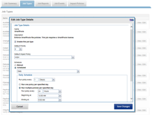
SnapRevert can be manually run from the OneFS WebUI by navigating to Cluster Management > Job Operations > Job Types > SnapRevert and clicking the ‘Start Job’ button.

Additionally, the job’s impact policy and relative priority can also be adjusted, if desired:

Before a snapshot is reverted, SnapshotIQ creates a point-in-time copy of the data that is being replaced. This enables the snapshot revert to be undone later, if necessary.

Additionally, individual files, rather than entire snapshots, can also be restored in place using the isi_file_revert command line utility.

# isi_file_revert
usage:
isi_file_revert -l lin -s snapid
isi_file_revert -p path -s snapid
-d (debug output)
-f (force, no confirmation)

This can help drastically simplify virtual machine management and recovery, for example.

Before creating snapshots, it’s worth considering that reverting a snapshot requires that a SnapRevert domain exist for the directory that is being restored. As such, it is recommended that you create SnapRevert domains for those directories while the directories are empty. Creating a domain for an empty (or sparsely populated) directory takes considerably less time.

Files may belong to multiple domains. Each file stores a set of domain IDs indicating which domain they belong to in their inode’s extended attributes table. Files inherit this set of domain IDs from their parent directories when they are created or moved. The domain IDs refer to domain settings themselves, which are stored in a separate system B-tree. These B-tree entries describe the type of the domain (flags), and various other attributes.

As mentioned, a Restricted-Write domain prevents writes to any files except by threads that are granted permission to do so. A SnapRevert domain that does not currently enforce Restricted-Write shows up as “(Writable)” in the CLI domain listing.

Occasionally, a domain will be marked as “(Incomplete)”. This means that the domain will not enforce its specified behavior. Domains created by job engine are incomplete if not all of the files that are part of the domain are marked as being members of that domain. Since each file contains a list of domains of which it is a member, that list must be kept up to date for each file. The domain is incomplete until each file’s domain list is correct.

In addition to SnapRevert, OneFS also currently uses domains for SyncIQ replication and SnapLock immutable archiving.

A SnapRevert domain needs to be created on a directory before it can be reverted to a particular point in time snapshot. As mentioned before, the recommendation is to create SnapRevert domains for a directory while the directory is empty.

The root path of the SnapRevert domain must be the same root path of the snapshot. For example, a domain with a root path of /ifs/data/marketing cannot be used to revert a snapshot with a root path of /ifs/data/marketing/archive.

For example, for snaphsot DailyBackup_04-27-2021_12:00 which is rooted at /ifs/data/marketing/archive:

  1. First, set the SnapRevert domain by running the DomainMark job (which marks all the files):
# isi job jobs start domainmark --root /ifs/data/marketing --dm-type SnapRevert
  1. Verify that the domain has been created:
# isi_classic domain list –l

In order to restore a directory back to the state it was in at the point in time when a snapshot was taken, you need to:

  • Create a SnapRevert domain for the directory.
  • Create a snapshot of a directory.

To accomplish this:

  1. First, identify the ID of the snapshot you want to revert by running the isi snapshot snapshots view command and picking your PIT (point in time).

For example:

# isi snapshot snapshots view DailyBackup_04-27-2021_12:00

ID: 38

Name: DailyBackup_04-27-2021_12:00

Path: /ifs/data/marketing

Has Locks: No

Schedule: daily

Alias: -

Created: 2021-04-27T12:00:05

Expires: 2021-08-26T12:00:00

Size: 0b

Shadow Bytes: 0b

% Reserve: 0.00%

% Filesystem: 0.00%

State: active
  1. Revert to a snapshot by running the isi job jobs start command. The following command reverts to snapshot ID 38 named DailyBackup_04-27-2021_12:00:
# isi job jobs start snaprevert --snapid 38

This can also be done from the WebUI, by navigating to Cluster Management > Job Operations > Job Types > SnapRevert and clicking the ‘Start Job’ button.

OneFS automatically creates a snapshot right before the SnapRevert process reverts the specified directory tree. The naming convention for these snapshots is of the form: <snapshot_name>.pre_revert.*

# isi snap snap list | grep pre_revert
39 DailyBackup_04-27-2021_12:00.pre_revert.1655328160 /ifs/data/marketing

This allows for an easy roll-back of a SnapRevert if the desired results are not achieved.

Note that, if a domain is currently preventing the modification or deletion of a file, a protection domain cannot be created on a
directory that contains that file. For example, if files under /ifs/data/smartlock are set to a WORM state by a
SmartLock domain, OneFS will not allow a SnapRevert domain to be created on /ifs/data/.

If desired or required, SnapRevert domains can also be deleted using the job engine CLI. For example, to delete the SnapRevert domain at /ifs/data/marketing:

# isi job jobs start domainmark --root /ifs/data/marketing --dm-type SnapRevert --delete

How To Configure NFS over RDMA

Starting from OneFS 9.2.0.0, NFSv3 over RDMA is introduced for better performance. Please refer to Chapter 6 of OneFS NFS white paper for the technical details. This article provides guidance on using the NFSv3 over RDMA feature with your OneFS clusters. Note that the OneFS NFSv3 over RDMA functionality requires that any clients are ROCEv2 capable. As such, client-side configuration is also needed.

OneFS Cluster configuration

To use NFSv3 over RDMA, your OneFS cluster hardware must meet requirements:

  • Node type: All Gen6 (F800/F810/H600/H500/H400/A200/A2000), F200, F600, F900
  • Front end network: Mellanox ConnectX-3 Pro, ConnectX-4 and ConnectX-5 network adapters that deliver 25/40/100 GigE speed.

1. Check your cluster network interfaces have ROCEv2 capability by running the following command and noting the interfaces that report ‘SUPPORTS_RDMA_RRoCE’. This check is only available on the CLI.

# isi network interfaces list -v

2. Create an IP pool that contains ROCEv2 capable network interface.

(CLI)

# isi network pools create --id=groupnet0.40g.40gpool1 --ifaces=1:40gige- 1,1:40gige-2,2:40gige-1,2:40gige-2,3:40gige-1,3:40gige-2,4:40gige-1,4:40gige-2 --ranges=172.16.200.129-172.16.200.136 --access-zone=System --nfsv3-rroce-only=true

(WebUI) Cluster management –> Network configuration

3. Enable NFSv3 over RDMA feature by running the following command.

(CLI)

# isi nfs settings global modify --nfsv3-enabled=true --nfsv3-rdma-enabled=true

(WebUI) Protocols –> UNIX sharing(NFS) –> Global settings

4. Enable OneFS cluster NFS service by running the following command.

(CLI)

# isi services nfs enable

(WebUI) See step 3

5. Create NFS export by running the following command. The –map-root-enabled=false is used to disable NFS export root-squash for testing purpose, which allows root user to access OneFS cluster data via NFS.

(CLI)

# isi nfs exports create --paths=/ifs/export_rdma --map-root-enabled=false

(WebUI) Protocols –> UNIX sharing (NFS) –> NFS exports

NFSv3 over RDMA client configuration

Note: As the client OS and Mellanox NICs may vary in your environment, you need to look for your client OS documentation and Mellanox documentation for the accurate and detailed configuration steps. This section only demonstrates an example configuration using our in-house lab equipment.

To use NFSv3 over RDMA service of OneFS cluster, your NFSv3 client hardware must meet requirements:

  • RoCEv2 capable NICs: Mellanox ConnectX-3 Pro, ConnectX-4, ConnectX-5, and ConnectX-6
  • NFS over RDMA Drivers: Mellanox OpenFabrics Enterprise Distribution for Linux (MLNX_OFED) or OS Distributed inbox driver. It is recommended to install Mellanox OFED driver to gain the best performance.

If you just want to have a functional test on the NFSv3 over RDMA feature, you can set up Soft-RoCE for your client.

Set up a RDMA capable client on physical machine

In the following steps, we are using the Dell PowerEdge R630 physical server with CentOS 7.9 and Mellanox ConnectX-3 Pro installed.

  1. Check OS version by running the following command:
# cat /etc/redhat-release

CentOS Linux release 7.9.2009 (Core)


2. Check the network adapter model and information. From the output, we can find the ConnectX-3 Pro is installed, and the network interfaces are named 40gig1 and 40gig2.

# lspci | egrep -i --color 'network|ethernet'

01:00.0 Ethernet controller: Intel Corporation 82599ES 10-Gigabit SFI/SFP+ Network Connection (rev 01)

01:00.1 Ethernet controller: Intel Corporation 82599ES 10-Gigabit SFI/SFP+ Network Connection (rev 01)

03:00.0 Ethernet controller: Mellanox Technologies MT27520 Family [ConnectX-3 Pro]

05:00.0 Ethernet controller: Intel Corporation I350 Gigabit Network Connection (rev 01)

05:00.1 Ethernet controller: Intel Corporation I350 Gigabit Network Connection (rev 01)

# lshw -class network -short

H/W path

==========================================================

/0/102/2/0&nbsp;&nbsp;&nbsp;&nbsp;&nbsp;&nbsp;&nbsp;&nbsp;&nbsp;&nbsp; 40gig1&nbsp;&nbsp;&nbsp;&nbsp; network&nbsp;&nbsp;&nbsp;&nbsp;&nbsp;&nbsp;&nbsp; MT27520 Family [ConnectX-3 Pro]

/0/102/3/0&nbsp;&nbsp;&nbsp;&nbsp;&nbsp;&nbsp;&nbsp;&nbsp;&nbsp;&nbsp;&nbsp;&nbsp;&nbsp;&nbsp;&nbsp;&nbsp;&nbsp;&nbsp;&nbsp;&nbsp;&nbsp; network&nbsp;&nbsp;&nbsp;&nbsp;&nbsp;&nbsp;&nbsp; 82599ES 10-Gigabit SFI/SFP+ Network Connection

/0/102/3/0.1&nbsp;&nbsp;&nbsp;&nbsp;&nbsp;&nbsp;&nbsp;&nbsp;&nbsp;&nbsp;&nbsp;&nbsp;&nbsp;&nbsp;&nbsp;&nbsp;&nbsp;&nbsp;&nbsp; network&nbsp;&nbsp;&nbsp;&nbsp;&nbsp;&nbsp;&nbsp; 82599ES 10-Gigabit SFI/SFP+ Network Connection

/0/102/1c.4/0&nbsp;&nbsp;&nbsp;&nbsp;&nbsp;&nbsp;&nbsp; 1gig1&nbsp;&nbsp;&nbsp;&nbsp;&nbsp; network&nbsp;&nbsp;&nbsp;&nbsp;&nbsp;&nbsp;&nbsp; I350 Gigabit Network Connection

/0/102/1c.4/0.1&nbsp;&nbsp;&nbsp;&nbsp;&nbsp; 1gig2&nbsp;&nbsp;&nbsp;&nbsp;&nbsp; network&nbsp;&nbsp;&nbsp;&nbsp;&nbsp;&nbsp;&nbsp; I350 Gigabit Network Connection

/3&nbsp;&nbsp;&nbsp;&nbsp;&nbsp;&nbsp;&nbsp;&nbsp;&nbsp;&nbsp;&nbsp;&nbsp;&nbsp;&nbsp;&nbsp;&nbsp;&nbsp;&nbsp; 40gig2&nbsp;&nbsp;&nbsp;&nbsp; network&nbsp;&nbsp;&nbsp;&nbsp;&nbsp;&nbsp;&nbsp; Ethernet interface

3. Find the suitable Mellanox OFED driver version from Mellanox website. As of MLNX_OFED v5.1, ConnectX-3 Pro are no longer supported and can be utilized through MLNX_OFED LTS version. See Figure 3. If you are using ConnectX-4 and above, you can use the latest Mellanox OFED version.

  • MLNX_OFED LTS Download

An important note: the NFSoRDMA module was removed from the Mellanox OFED 4.0-2.0.0.1 version, then it was added again in Mellanox OFED 4.7-3.2.9.0 version. Please refer to Release Notes Change Log History for the details.

4. Download the MLNX_OFED 4.9-2.2.4.0 driver for ConnectX-3 Pro to your client.

5. Extract the driver package, find the “mlnxofedinstall” script to install the driver. As of MLNX_OFED v4.7, NFSoRDMA driver is no longer installed by default. In order to install it over a supported kernel, add the “–with-nfsrdma” installation option to the “mlnxofedinstall” script. Firmware update is skipped in this example, please update it as needed.

#  ./mlnxofedinstall --with-nfsrdma --without-fw-update

Logs dir: /tmp/MLNX_OFED_LINUX.19761.logs

General log file: /tmp/MLNX_OFED_LINUX.19761.logs/general.log

Verifying KMP rpms compatibility with target kernel...

This program will install the MLNX_OFED_LINUX package on your machine.

Note that all other Mellanox, OEM, OFED, RDMA or Distribution IB packages will be removed.

Those packages are removed due to conflicts with MLNX_OFED_LINUX, do not reinstall them.

Do you want to continue?[y/N]:y

Uninstalling the previous version of MLNX_OFED_LINUX

rpm --nosignature -e --allmatches --nodeps mft

Starting MLNX_OFED_LINUX-4.9-2.2.4.0 installation ...

Installing mlnx-ofa_kernel RPM

Preparing...                          ########################################

Updating / installing...

mlnx-ofa_kernel-4.9-OFED.4.9.2.2.4.1.r########################################

Installing kmod-mlnx-ofa_kernel 4.9 RPM
...

Preparing...                          ########################################

mpitests_openmpi-3.2.20-e1a0676.49224 ########################################

Device (03:00.0):

03:00.0 Ethernet controller: Mellanox Technologies MT27520 Family [ConnectX-3 Pro]

Link Width: x8

PCI Link Speed: 8GT/s

Installation finished successfully.

Preparing...                          ################################# [100%]

Updating / installing...

1:mlnx-fw-updater-4.9-2.2.4.0      ################################# [100%]

Added 'RUN_FW_UPDATER_ONBOOT=no to /etc/infiniband/openib.conf

Skipping FW update.

To load the new driver, run:

# /etc/init.d/openibd restart

6. Load the new driver by running the following command. Unload all module that is in use prompted by the command.

# /etc/init.d/openibd restart

Unloading HCA driver:&nbsp;&nbsp;&nbsp;&nbsp;&nbsp;&nbsp;&nbsp;&nbsp;&nbsp;&nbsp;&nbsp;&nbsp;&nbsp;&nbsp;&nbsp;&nbsp;&nbsp;&nbsp;&nbsp;&nbsp;&nbsp;&nbsp;&nbsp;&nbsp;&nbsp;&nbsp;&nbsp;&nbsp;&nbsp;&nbsp;&nbsp;&nbsp;&nbsp;&nbsp;&nbsp;&nbsp;&nbsp; [&nbsp; OK&nbsp; ]

Loading HCA driver and Access Layer:&nbsp;&nbsp;&nbsp;&nbsp;&nbsp;&nbsp;&nbsp;&nbsp;&nbsp;&nbsp;&nbsp;&nbsp;&nbsp;&nbsp;&nbsp;&nbsp;&nbsp;&nbsp;&nbsp;&nbsp;&nbsp;&nbsp; [&nbsp; OK&nbsp; ]<br>

7. Check the driver version to ensure the installation is successful.

# ethtool -i 40gig1

driver: mlx4_en

version: 4.9-2.2.4

firmware-version: 2.36.5080

expansion-rom-version:

bus-info: 0000:03:00.0

supports-statistics: yes

supports-test: yes

supports-eeprom-access: no

supports-register-dump: no

supports-priv-flags: yes

8. Check the NFSoRDMA module is also installed. If you are using a driver downloaded from server vendor website (like Dell PowerEdge server) rather than Mellanox website, the NFSoRDMA module may not be included in the driver package. You must obtain the NFSoRDMA module from Mellanox driver package and install it.

# yum list installed | grep nfsrdma

kmod-mlnx-nfsrdma.x86_64&nbsp;&nbsp;&nbsp;&nbsp;&nbsp;&nbsp;&nbsp;&nbsp;&nbsp;&nbsp;&nbsp;&nbsp; 5.0-OFED.5.0.2.1.8.1.g5f67178.rhel7u8

9. Mount NFS export with RDMA protocol.

#&nbsp; mount -t nfs -vo nfsvers=3,proto=rdma,port=20049 172.16.200.29:/ifs/export_rdma /mnt/export_rdma

mount.nfs: timeout set for Tue Feb 16 21:47:16 2021

mount.nfs: trying text-based options 'nfsvers=3,proto=rdma,port=20049,addr=172.16.200.29'

Useful reference for Mellanox OFED documentation:

Set up Soft-RoCE client for functional test only

Soft-RoCE (also known as RXE) is a software implementation of RoCE that allows RoCE to run on any Ethernet network adapter whether it offers hardware acceleration or not. Soft-RoCE is released as part of upstream kernel 4.8 (or above). It is intended for users who wish to test RDMA on software over any 3rd party adapters.

In the following example configuration, we are using CentOS 7.9 virtual machine to configure Soft-RoCE. Since Red Hat Enterprise Linux 7.4, the Soft-RoCE driver is already merged into the kernel.

1. Install required software packages.

# yum install -y nfs-utils rdma-core libibverbs-utils

2. Start Soft-RoCE.

# rxe_cfg start

3. Get status, which will display ethernet interfaces

# rxe_cfg status

rdma_rxe module not loaded

Name   Link  Driver  Speed  NMTU  IPv4_addr        RDEV  RMTU

ens33  yes   e1000          1500  192.168.198.129

4. Verify RXE kernel module is loaded by running the following command, ensure that you see rdma_rxe in the list of modules.

# lsmod | grep rdma_rxe

rdma_rxe              114188  0

ip6_udp_tunnel         12755  1 rdma_rxe

udp_tunnel             14423  1 rdma_rxe

ib_core               255603  13 rdma_cm,ib_cm,iw_cm,rpcrdma,ib_srp,ib_iser,ib_srpt,ib_umad,ib_uverbs,rdma_rxe,rdma_ucm,ib_ipoib,ib_isert

5. Create a new RXE device/interface by using rxe_cfg add <interface from rxe_cfg status>.

# rxe_cfg add ens33

6. Check status again, make sure the rxe0 was added under RDEV (rxe device)

# rxe_cfg status

Name   Link  Driver  Speed  NMTU  IPv4_addr        RDEV  RMTU

ens33  yes   e1000          1500  192.168.198.129  rxe0  1024  (3)

7. Mount NFS export with RDMA protocol.

# mount -t nfs -o nfsvers=3,proto=rdma,port=20049 172.16.200.29:/ifs/export_rdma /mnt/export_rdma

You can refer to Red Hat Enterprise Linux configuring Soft-RoCE for more details.

OneFS Groupnet and Network Tenancy

In OneFS, the Groupnet networking object, is an integral part of multi-tenancy support.

Multi-Tenancy, within the SmartConnect context, refers to the ability of a OneFS cluster to simultaneously handle more than one set of networking configuration. Multi-Tenant Resolver or MTDNS refers to the subset of that feature pertaining specifically to hostname resolution against DNS nameservers.

Groupnets sit above existing objects, subnets and address pools, in the object hierarchy. Groupnets may contain one or more subnets, and every subnet exists within one (and only one) groupnet.

All newly configured and upgraded clusters start out with one default groupnet named groupnet0. Customers who any not interested in multi-tenancy will simply use this single groupnet and never make any others.

Groupnets are the configuration point for DNS settings, which had previously been global to the cluster. Nameservers and other DNS options are now properties of the groupnet object, and configured there in the CLI isi network groupnets and WebUI. Conceptually it would be appropriate to think of groupnets as a networking tenant; different groupnets are used to allow portions of the cluster to have different networking properties for name resolution, etc. The recommendation is to create a groupnet for each different DNS namespace that’s required.

Note that OneFS also has a networking object termed a netgroup, used to manage network access. Groupnets are unrelated to netgroups.

The DNS cache is also multi-tenant-aware, so it maintains separate instances for individual groupnets. Each groupnet may specify whether to enable caching or not: It’s enabled by default, and this is the recommended setting for both performance and reliability.

A number of global cache timeout settings are also available. The CLI for managing them is isi network dnscache, and more detail is available via the isi-network(8) manpage. Note, the isi_cbind command retains the same syntax and usage.

Access Zones and groupnets are tightly coupled, and must be specified at zone creation. Zones may only be associated with address pools and authentication providers that share the same groupnet. For example, the following command creates an access zone with groupnet association:

# isi zone zones create lab1 /ifs/data/lab1 –groupnet groupnet1

Or from the WebUI:

In a multi-tenant environment, authentication providers (AD, LDAP, etc) need to know which networking properties they should use, and therefore need to be bound to a groupnet. This happens directly at creation time. A groupnet may be specified via the CLI using the create option –groupnet. Or, if unspecified, the default groupnet0 will be assumed. For example:

# isi auth ads create lab.isilon.com Administrator –groupnet groupnet1

Or via the WebUI:

Once created, authentication providers may only be used by access zones within the same groupnet. If a provider is created and associated with the wrong groupnet, it must be deleted and re-created with the correct one.

In general, services or protocols which work face end users and are access-zone aware are also supported with Groupnets. Administrative and infrastructure services like WebUI, SSH, SyncIQ, and so on are not.

When creating new network tenants, the recommended process is:

  1. Groupnet, create and specify nameservers
  2. Access zone, create and associate with groupnet (which must already be created)
  3. Subnet, create within groupnet (which must already be created)
  4. Address pool, create within subnet (which must already be created) and associate with access zone (which must already be created)
  5. Authentication provider, create and associate with groupnet (which must already be created)
  6. Access zone, modify to add authentication provider

Attempting to do things out of this order may create other challenges. For example, if an access zone has not already been created in a groupnet, you will be unable to add an address pool, since it requires an access zone to already be present.

Some customers have a set of host information they want available without DNS and instead wish to specify locally on the cluster. A file /etc/local/hosts can be created for specifying network hosts manually, and, by default, any entries it contains will be used in groupnet0. However, additional groupnets can also be listed in square brackets. The lines that follow each will be used to populate a hosts file specific to that groupnet. For example:

# cat /etc/local/hosts

1.2.3.4    hosta.foo.com  # default groupnet0

1.2.3.5    hostb.foo.com  # default groupnet0

[groupnet1]

5.6.7.8    hostc.bar.com  # groupnet1

5.6.7.9    hostd.bar.com  # groupnet1

Please be aware of the following considerations:

  • Despite using different nameservers, the address space is still assumed to be unique. OneFS does not permit IP address conflicts even if the conflicting addresses are in different groupnets.
  • Names of authentication providers also must be unique, even across groupnets. You cannot, for example, have two AD providers joined to the same domain name even if they are in different groupnets (and therefore the same name may resolve to different addresses and machines.)
  • It is permissable to have a configuration wherein some nodes are unable to route to nameservers of some groupnets, although that practice is not recommended for the default groupnet. In this case all tasks associated with these limited groupnets, including CLI and WebUI administration, must be performed on nodes that are capable of these lookups.

So, the SmartConnect hierarchy encompasses the following network objects:

  • Groupnet: Represents a ‘network tenant and can contain a collection of subnets’. It also contains information about DNS resolution of external authentication providers.
  • Subnet: Contains a netmask and an IP base address, together which define a range of IP addresses. A subnet can be either IPv4 or IPv6. A subnet contains a collection of IP pools.
  • IP Pool: An IP Pool is an object that contains a set of IP addresses within a subnet and configuration on how they are used. An IP Pool can be associated with a set of DNS host names. An IP pool may be either static or dynamic, based on the –alloc-method setting on the IP Pool. This attribute indicates whether the IPs in the pool can move back and forth between nodes when a node goes down.
  • Network Rule: A network rule contains specifications on how to auto-populate a pool with interfaces. For example, a rule could specify that the pool contains the ext-1 interface on all nodes. If a pool contains more than one network rule, they are considered additive.

Network objects are specified by their network ID, which is a series of network name identifiers separated by either periods or colons.

To create a SmartConnect groupnet and configure DNS client settings, run the isi network groupnet create command. For example, the following command creates a groupnet and adds a DNS server with caching enabled:

# isi network groupnet create groupnet1 --dns-servers=192.168.10.10 --dns-cache-enabled=true

Or via the WebUI:

Unless it’s the default, a groupnet can be fairly easily removed from SmartConnect. However, if a groupnet is associated with an access zone, removing it may adversely impact other areas of the cluster config. The recommended order for removing a groupnet is:

  1. Delete IP address pools in subnets associated with the groupnet.
  2. Delete subnets associated with the groupnet.
  3. Delete authentication providers associated with the groupnet.
  4. Delete access zones associated with the groupnet.

To delete a groupnet, run:

# isi network groupnet delete <groupnet_name>

Note that in several cases, the association between a groupnet and another OneFS component, such as access zones or authentication providers, is absolute and can’t be modified to associate it with another groupnet. For example, the following command unsuccessfully attempts to delete groupnet1 which is still associated with an access zone:

# isi network modify groupnet groupnet1

Groupnet groupnet1 is not deleted; groupnet can’t be deleted while pointed at by zone(s) zoneB

To modify groupnet attributes, including the name, supported DNS servers, and DNS configuration settings, run the isi network groupnet modify command. For example:

# isi network groupnet modify groupnet1 –dns-search=lab.isilon.com,test.isilon.com

To retrieve and sort a list of groupnets by ID in descending order, run the isi network groupnets list command. For example:

# isi network groupnets list --sort=id --descending

ID DNS Cache DNS Search DNS Servers Subnets

------------------------------------------------------------

groupnet2 True lab.isilon.com 192.168.2.75 subnet2

192.168.2.67 subnet4

groupnet1 True 192.168.2.92 subnet1

192.168.2.83 subnet3

groupnet0 False 192.168.2.11 subnet0

192.168.2.20

--------

Total: 3

To view the details of a specific groupnet, run the isi network groupnets view command. For example:

# isi network groupnets view groupnet1

ID: groupnet1

Name: groupnet1

Description: Lab storage groupnet

DNS Cache Enabled: True

DNS Options: -

DNS Search: lab.isilon.com

DNS Servers: 192.168.1.75, 172.16.2.67

Server Side DNS Search: True

Allow Wildcard Subdomains: True

Subnets: subnet1, subnet3

Groupnet information can also be viewed, created, deleted and modified from the WebUI by navigating to: Cluster Management -> Network Configuration -> External Network

So there we have it. The groupnet is the networking cornerstones of the OneFS multi-tenancy stack.

The OneFS protocols and services which are multi-tenant aware and can work with multiple groupnets include:

  • SMB
  • NFS (including NSM and NLM)
  • HDFS
  • S3
  • Authentication (AD, LDAP, NIS, Kerberos)

OneFS Cluster Quick Checks

OneFS brings simplicity, scalability, and ease of use to unstructured data management complexity. However, as with many things in life, an ounce of prevention is key to keeping a cluster happily humming along. As such, the following daily, monthly, and quarterly checks provide a quick and easy method for keeping an eye on a PowerScale environment and ensuring smooth cluster operation.

1 Daily Checks
Daily health checks are important to ensure a cluster is operating at optimal performance and capacity. These checks require minimal effort and develop familiarity: Ie. Becoming aware of alerts that point to an area of interest, or something requiring further investigation, before it becomes something larger.
Category Check Method Option(s) Description / Recommendation
Health Score CloudIQ, Alerts Target a Health Score of 100
Cluster Capacity WebUI, CLI, DataIQ, InsightIQ, CloudIQ, Alerts Maintain a storage utilization below 90%
Events and Alerts WebUI, CLI, Alerts Address all Hardware and Software Alerts as they occur
 

2 Monthly Checks
Monthly cluster health checks help ensure the environment is performing as expected, while also providing an opportunity to measure progress against service level objectives and review new OneFS feature enhancements.
Category Check Method Option(s) Description / Recommendation
Upgrade Strategy Isilon On Cluster Analysis (IOCA)

Current OneFS Patch

OneFS and Firmware code currency.

ioca -u <target code version>

Example: ioca -u 8.2.2 to get latest upgrade plan

SRS/Alerts/Events/Email WebUI, CLI, SRS Confirm that all alerting and notifications are operating as planned
Failed Drive Status WebUI, CLI Review drive status and ensure that all drives that have SmartFailed have been replaced
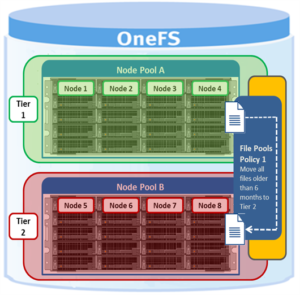
SmartPools WebUI, CLI Review SmartPools settings and Node Pools utilization to identify if tiering changes are necessary
SnapshotIQ WebUI, CLI Snapshot utilization above 10% or any single snapshot possessing excessive size

[Ex. fsa snapshot]

SyncIQ WebUI, CLI Check the SyncIQ configuration to ensure RPO/RTO targets and required data is being replicated as needed
Monitoring Tools CloudIQ, DataIQ, InsightIQ Confirm that all monitoring tools are continuing to gather data from all storage devices
Healthcheck Framework CLI Ensure that the latest Healthcheck Framework checks are installed and Healthcheck Assessment is executed
DSA/DTA

(Dell Security Advisory/Dell Technical Advisory)

Isilon/PowerScale Alert Subscription, Service360

DSA | DTA

Verify if DSA/DTA is applicable to your cluster and if so, take immediate action


3 Quarterly Checks
Quarterly cluster health checks help ensure that the environment is running at optimal performance and capacity while at the same time provide an opportunity to evaluate against broader business level objectives and review new OneFS feature enhancements..
Category Check Method Option(s) Description / Recommendation
OneFS and Firmware Update Considerations Dell Technologies Support Site (https://www.dell.com/support/home/)

Target Code Information

Contact your Unstructured Data Solutions Systems Engineer

Review newer OneFS versions to determine the beneficial of upgrading to a newer release. In addition to OneFS, node and drive firmware should also be considered. Obtain the latest code information via the Dell EMC support site and utilize the Dell EMC team for the upgrade where possible.
OneFS Patch Updates Dell Technologies Support Site (https://www.dell.com/support/home/) Check the latest Roll-up Patches (RUPs) and upgrade as needed.
Monitoring Tools Updates InsightIQ, DataIQ, CloudIQ, SRS Review all monitoring tools to determine if upgrades are needed.
Capacity Trending InsightIQ, DataIQ, CloudIQ Evaluate capacity growth trends to determine if additional node purchase will be required over the next 6 months.

Further details on OneFS recommended practices and check list items are available in the OneFS Best Practices white paper.

Isilon PAPI, SDK, RAN Samples

I’ve attached some python sample codes (notebook) in this post to help better understanding how to leverage our Isilon PAPI or SDK for day to day jobs on PowerScale or even some customization. To use these sample, you may want to install the Jupyter notebook first (https://jupyter.org/install ) and then you can do the live debug to see the real time output.

The samples including:

  1. 01 Getting Started with Python Requests Module
  2. Cluster Config
  3. Getting Started with Isilon Python SDK
  4. NFS Exports
  5. SMB Shares SDK
  6. SMB Shares
  7. User Accounts
  8. Quotas
  9. Snapshots
  10. File System Access API RAN

…will continue to add more

(Great thanks to Jim Sims for the contribution.)

OneFS and Designing Large Clusters

Received a couple of recent enquiries around how to best accommodate big, unstructured datasets and varied workloads, so it seemed like an interesting topic to cover in a blog article.

Essentially, when it comes to designing and scaling large PowerScale clusters for large quantities and growth rates of data, there are some key tenets to bear in mind. These include:

  • Strive for simplicity
  • Plan ahead
  • Just because you can doesn’t necessarily mean you should

Distributed systems tend to be complex by definition, and this is amplified at scale. OneFS does a good job of simplifying cluster administration and management, but a solid architectural design and growth plan is crucial. Because of its single, massive volume and namespace, OneFS is viewed by many as a sort of ‘storage Swiss army knife’. Left unchecked, this methodology can result in unnecessary complexities as a cluster scales. As such, decision making that favors simplicity is key.

Despite OneFS’ extensibility, allowing a PowerScale system to simply grow organically into a large cluster often results in various levels of technical debt. In the worst case, some issues may have grown so large that it becomes impossible to correct the underlying cause. This is particularly true in instances where a small cluster is initially purchased for an archive or low performance workload and with a bias towards cost optimized storage. As the administrators realize how simple and versatile their clustered storage environment is, more applications and workflows are migrated to OneFS. This kind of haphazard growth, such as morphing from a low-powered, near-line platform into something larger and more performant, can lead to all manner of scaling challenges. However, compromises, living with things, or fixing issues that could have been avoided can usually be mitigated by starting out with a scalable architecture, workflow and expansion plan.

Beginning the process with a defined architecture, sizing and expansion plan is key. What do you anticipate the cluster, workloads, and client access levels will look like in six months, one year, three years, or five years? How will you accommodate the following as the cluster scales?

  • Contiguous rack space for expansion
  • Sufficient power & Cooling
  • Network infrastructure
  • Backend switch capacity
  • Availability SLAs
  • Serviceability and spares plan
  • Backup and DR plans
  • Mixed protocols
  • Security, access control, authentication services, and audit
  • Regulatory compliance and security mandates
  • Multi-tenancy and separation
  • Bandwidth segregation – client I/O, replication, etc.
  • Application and workflow expansion

There are really two distinct paths to pursue when initially designing an OneFS clustered storage architecture for a large and/or rapidly growing environment – particularly one that includes a performance workload element to it. These are:

  • Single Large Cluster
  • Storage Pod Architecture

A single large, or extra-large, cluster is often deployed to support a wide variety of workloads and their requisite protocols and performance profiles – from primary to archive – within a single, scalable volume and namespace. This approach, referred to as a ‘data lake architecture’, usually involves more than one style of node.

OneFS can support up to fifty separate tenants in a single cluster, each with their own subnet, routing, DNS, and security infrastructure. OneFS’ provides the ability to separate data layout with SmartPools, export and share level segregation, granular authentication and access control with Access Zones, and network partitioning with SmartConnect, subnets, and VLANs.

Furthermore, analytics workloads can easily be run against the datasets in a single location and without the need for additional storage and data replication and migration.

For the right combination of workloads, the data lake architecture has many favorable efficiencies of scale and centralized administration.

Another use case for large clusters is in a single workflow deployment, for example as the content repository for the asset management layer of a content delivery workflow. This is a considerably more predictable, and hence simpler to architect, environment that the data lake.

Often, as in the case of a MAM for streaming playout for example, a single node type is deployed. The I/O profile is typically heavily biased towards streaming reads and metadata reads, with a smaller portion of writes for ingest.

There are trade-offs to be aware of as cluster size increases into the extra-large cluster scale. The larger the node count, the more components are involved, which increases the likelihood of a hardware failure. When the infrastructure becomes large and complex enough, there’s more often than not a drive failing or a node in an otherwise degraded state. At this point, the cluster can be in a state of flux such that composition, or group, changes and drive rebuilds/data re-protects will occur frequently enough that they can start to significantly impact the workflow.

Higher levels of protection are required for large clusters, which has a direct impact on capacity utilization. Also, cluster maintenance becomes harder to schedule since many workflows, often with varying availability SLAs, need to be accommodated.

Additional administrative shortcomings that also need to be considered when planning on an extra-large cluster include that InsightIQ only supports monitoring clusters of up to eighty nodes and the OneFS Cluster Event Log (CELOG) and some of the cluster WebUI and CLI tools can prove challenging at an extra-large cluster scale.

That said, there can be wisdom in architecting a clustered NAS environment into smaller buckets and thereby managing risk for the business vs putting the ‘all eggs in one basket’. When contemplating the merits of an extra-large cluster, also consider:

  • Performance management,
  • Risk management
  • Accurate workflow sizing
  • Complexity management.

A more practical approach for more demanding, HPC, and high-IOPS workloads often lies with the Storage Pod architecture. Here, design considerations for new clusters revolve around multiple (typically up to 40 node) homogenous clusters, with each cluster itself acting as a fault domain – in contrast to the monolithic extra-large cluster described above.

Pod clusters can easily be tailored to the individual demands of workloads as necessary. Optimizations per storage pod can include size of SSDs, drive protection levels, data services, availability SLAs, etc. In addition, smaller clusters greatly reduce the frequency and impact of drive failures and their subsequent rebuild operations. This, coupled with the ability to more easily schedule maintenance, manage smaller datasets, simplify DR processes, etc, can all help alleviate the administrative overhead for a cluster.

A Pod infrastructure can be architected per application, workload, similar I/O type (ie. streaming reads), project, tenant (ie. business unit), availability SLA, etc. This pod approach has been successfully adopted by a number of large PowerScale customers in industries such as semiconductor, automotive, life sciences, and others with demanding performance workloads.

This Pod architecture model can also fit well for global organizations, where a cluster is deployed per region or availability zone. An extra-large cluster architecture can be usefully deployed in conjunction with Pod clusters to act as a centralized disaster recovery target, utilizing a hub and spoke replication topology. Since the centralized DR cluster will be handling only predictable levels of replication traffic, it can be architected using capacity-biased nodes.

Before embarking upon either a data lake or Pod architectural design, it is important to undertake a thorough analysis of the workloads and applications that the cluster(s) will be supporting.

Despite the flexibility offered by the data lake concept, not all unstructured data workloads or applications are suitable for a large PowerScale cluster. Each application or workload that is under consideration for deployment or migration to a cluster should be evaluated carefully. Workload analysis involves reviewing the ecosystem of an application for its suitability. This requires an understanding of the configuration and limitations of the infrastructure, how clients see it, where data lives within it, and the application or use cases in order to determine:

  • How the application works?
  • How users interact with the application?
  • What is the network topology?
  • What are the workload-specific metrics for networking protocols, drive I/O, and CPU & memory usage?

OneFS Capacity Management

There have been several discussion recently around the effects of high capacity utilization on cluster performance. Capacity management is a vital part of OneFS system administration and would seem to warrant a blog article.

Because OneFS is a single, scalable file system, unencumbered by underlying volume management requirements, it can lead to reduce vigilance on cluster capacity utilization. While the cluster will fire alerts before things become critical, not all sites have additional nodes on hand, sitting around waiting for cluster expansion. The reality is there’s a lead time between ordering and taking delivery of new hardware. As such, it pays to be proactive when it comes to cluster capacity management.

When a cluster, or any of its nodepools, becomes more than 90% full, OneFS can experience slower performance and possible workflow interruptions in high-transaction or write-speed-critical operations. Furthermore, when a cluster or pool approaches full capacity (ie. over 95% full), the following issues can arise:

  • Substantially slower performance
  • Workflow disruptions – failed file operations and inability to write data
  • Inability to make configuration changes or run commands to delete data and free up space

Allowing a cluster or pool to fill can put the cluster into a non-operational state that can take significant time (hours, or even days) to correct. Therefore, it is important to keep your cluster or pool from becoming full. To ensure that a cluster or its constituent pools do not run out of space:

  • Add new nodes to existing clusters or pools
  • Replace smaller-capacity nodes with larger-capacity nodes
  • Create more clusters.

OneFS will notify when cluster capacity starts to reach levels of concern. If the warning events and alerts are not heeded, the following error messages can be displayed when attempting to write to a full, or nearly full, cluster or pool:

Error Message Where Error is Displayed
The operation can’t be completed because the disk “<share name>” is full. OneFS WebUI, or the command line interface on an NFS client.
No space left on device. OneFS WebUI, or the command line interface on an NFS client, etc.
No available space. OneFS WebUI, or the command line interface on a Windows or SMB client.
ENOSPC (error code) Written to the cluster’s /var/log/messages file. This error code will be embedded in another message.
Failed to satisfy layout preference. Written to the cluster’s /var/log/messages file
Disk Quota Exceeded. Cluster command line interface, or an NFS client when you encounter a Snapshot Reserve limitation.

When deciding to add new nodes to an existing cluster or pool, contact your sales team to order the nodes well in advance of the cluster or pool running short on space. The recommendation is to start planning for additional capacity when the cluster or pool reaches 75% full. This will allow sufficient time to receive and install the new hardware, while still maintaining sufficient free space.

Here’s the recommended timeline for cluster capacity planning purposes:

If your data availability and protection SLA varies across different data categories (for example, home directories, file services, etc), ensure that any snapshot, replication and backup schedules are configured accordingly to meet the required availability and recovery objectives, and fit within the overall capacity plan.

Consider configuring a separate accounting quota for /ifs/home and /ifs/data directories (or wherever data and home directories are provisioned) to monitor aggregate disk space usage and issue administrative alerts as necessary to avoid running low on overall capacity.

DataIQ and InsightIQ both provide detailed monitoring and trending functionality to help with capacity consumption projections and usage forecasting.

For optimal performance in any size cluster, the recommendation is to maintain at least 10% free space in each pool of a cluster.

To better protect smaller clusters (containing 3 to 7 nodes) the recommendation is to maintain 15 to 20% free space. A full smartfail of a node in smaller clusters may require more than one node’s worth of space. Keeping 15 to 20% free space can allow the cluster to continue to operate while support assists with recovery plans.

Also, it pays to plan for contingencies: Having a fully updated backup of your data can limit the risk of data loss if a node fails.

Maintaining appropriate protection levels

Ensure your cluster and pools are protected at the appropriate level. Every time you add nodes, re-evaluate protection levels. OneFS includes a ‘suggested protection’ function that calculates a recommended protection level based on cluster configuration, and alerts you if the cluster falls below this suggested level

OneFS supports several protection schemes. These include the ubiquitous +2d:1n, which protects against two drive failures or one node failure. Use the recommended protection level for a particular cluster configuration. This recommended level of protection is clearly marked as ‘suggested’ in the OneFS WebUI storage pools configuration pages, and is typically configured by default.

Monitoring cluster capacity

  • Configure alerts. Set up event notification rules so that you will be notified when the cluster begins to reach capacity thresholds. Make sure to enter a current email address in order to receive the notifications.
  • Monitor alerts. The cluster sends notifications when it has reached 95 percent and 99 percent capacity. On some larger clusters, 5 percent (or even 1 percent) capacity remaining might mean that a lot of space is still available, so you might be inclined to ignore these notifications. However, it is best to pay attention to the alerts, closely monitor the cluster, and have a plan in place to take action when necessary.
  • Monitor ingest rate. It’s important to understand the rate at which data is coming in to the cluster or pool. Options to do this include:
    • SNMP
    • SmartQuotas
    • FSAnalyze
    • DataIQ/InsightIQ
  • Use SmartQuotas to monitor and enforce administrator-defined storage limits. SmartQuotas manages storage use, monitors disk storage, and issues alerts when disk storage limits are exceeded. Although it does not provide the same detail of the file system that FSAnalyze does, SmartQuotas maintains a real-time view of space utilization so that you can quickly obtain the information you need.
  • Run FSAnalyze jobs. FSAnalyze is a job-engine job that the system runs to create data for file system analytics tools. FSAnalyze provides details about data properties and space usage within the /ifs directory. Unlike SmartQuotas, FSAnalyze updates its views only when the FSAnalyze job runs. Since FSAnalyze is a fairly low-priority job, it can sometimes be preempted by higher-priority jobs and therefore take a long time to gather all of the data.

Managing data

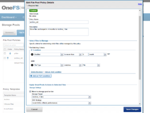
Regularly archive data that is rarely accessed and delete any unused and unwanted data. Ensure that pools do not become too full by setting up file pool policies to move data to other tiers and pools.

Provisioning additional capacity

To ensure that your cluster or pools do not run out of space, you can create more clusters, replace smaller-capacity nodes with larger-capacity nodes, or add new nodes to existing clusters or pools. If you decide to add new nodes to an existing cluster or pool, contact your sales representative to order the nodes long before the cluster or pool runs out of space. EMC recommends that you begin the ordering process when the cluster or pool reaches 80% used capacity. This will allow enough time to receive and install the new equipment and still maintain enough free space.

Managing snapshots

Sometimes a cluster has many old snapshots that consume significant capacity. Reasons for this include inefficient deletion schedules, degraded cluster preventing job execution, expired SnapshotIQ license, etc. Retaining only the snapshots required to support the data availability and protection SLAs will help guard against unintended capacity utilization.

Ensuring all nodes are supported and compatible

Each version of OneFS supports only certain nodes. Refer to the “OneFS and node compatibility” section of the PowerScale Supportability and Compatibility Guide for a list of which nodes are compatible with each version of OneFS. When upgrading OneFS, make sure that the new version supports your existing nodes. If it does not, you might need to replace the nodes.

Space and performance are optimized when all nodes in a pool are compatible. When new nodes are added to a cluster, OneFS automatically provisions nodes into pools with other nodes of compatible type, hard drive capacity, SSD capacity, and RAM. Occasionally, however, the system might put a node into an unexpected location. If you believe that a node has been placed into a pool incorrectly, contact Dell Technical Support for assistance. Different versions of OneFS have different rules regarding what makes nodes compatible

Enabling Virtual Hot Spare and Spillover

OneFS also provides a Virtual Hot Spare (VHS), who’s purpose is to keep space in reserve in case you need to smartfail drives when the cluster gets close to capacity. Enabling VHS will not give you more free space, but it will help protect your data in the event that space becomes scarce. VHS is enabled by default. It’s strongly recommended that you do not disable VHS unless directed by a Support engineer. If you disable VHS in order to free some space, the space you just freed will probably fill up again very quickly with new writes. At that point, if a drive were to fail, you might not have enough space to smartfail the drive and re-protect its data, potentially leading to data loss. If VHS is disabled and you upgrade OneFS, VHS will remain disabled. If VHS is disabled on your cluster, first check to make sure the cluster has enough free space to safely enable VHS, and then enable it.

Spillover allows data that is being sent to a full pool to be diverted to an alternate pool. Spillover is enabled by default on clusters that have more than one pool. If you have a SmartPools license on the cluster, you can disable Spillover. However, it is recommended that you keep Spillover enabled. If a pool is full and Spillover is disabled, you might get a “no space available” error but still have a large amount of space left on the cluster.

Run OneFS Healthchecks

Regularly run and review the OneFS health checks. These can be easily configured and managed from either the WebUI or CLI:

Use OneFS Healthchecks to confirm there are no current cluster issues and that OneFS’ configuration is as expected.