OneFS and CloudPools Upgrades

OneFS’ non-disruptive upgrade (NDU) functionality allows administrators to upgrade a cluster while their end user community continue to access data without error or interruption. During the OneFS rolling upgrade process, one node at a time is updated to the new code, and the active clients attached to it are automatically migrated to other nodes in the cluster. Partial upgrade is also supported, allowing a subset of cluster nodes can be upgraded, and the subset of nodes may also be grown during the upgrade. OneFS also permits an upgrade to be paused and resumed, enabling customers to span cluster upgrades over multiple smaller Maintenance Windows.

OneFS CloudPools v1.0 originally debuted back in the OneFS 8.0 release. The next major update, CloudPools v2.0, was delivered in OneFS 8.2 release, and introduced significant enhancements which included:

  • Support for AWS signature authentication version 4.
  • Network statistics per CloudPools account or file pool policy.
  • Support for Alibaba Cloud and Amazon C2S public cloud providers.
  • Full integration of CloudPools and data services like Snapshot, Sparse file handling, Quota, AVScan and WORM.
  • NDMP and SyncIQ support
  • Non-Disruptive Upgrade (NDU) support

CloudPools, like its SmartPools counterpart, uses the OneFS file pool policy engine to designate which data on a cluster should reside on which tier, or be archived to a cloud storage target. If files match the criteria specified in a file pool policy, the content of those files is moved to cloud storage when the job runs. Under the hood, CloudPools uses ‘SmartLink’ files within the /ifs namespace, each of which contains information about where to retrieve each file’s data blocks that have been cloud tiered. In CloudPools 1.0, these SmartLink v1 files, often referred to as ‘stubs’, do not behave like a normal file. By contrast, the SmartLink v2 files in CloudPools 2.0 are more like traditional files, each containing pointers to the CloudPools target where the data resides.

When a CloudPools 1.0 cluster is upgraded to OneFS 8.2 or later, a ‘changeover’ process is automatically initiated upon upgrade commit. This process is responsible for converting the v1 SmartLink files to v2, ensuring a seemless transition from CloudPools 1.0 to 2.0.

The following table outlines the upgrade paths available when transitioning from CloudPools 1.0 to 2.0:

Current OneFS Version Upgrade to OneFS 8.2 Upgrade to OneFS 8.2.1 with 5/2020 RUPs Upgrade to OneFS 8.2.2 with 5/2020 RUPs Upgrade to OneFS 9.x
OneFS 8.0 Discouraged Viable Recommended Highly recommended
OneFS 8.1 Discouraged Viable Recommended Highly recommended

In a SyncIQ environment with unidirectional replication, the SyncIQ target cluster should be upgraded before the source cluster. Conversely, for bi-directional replication, the recommendation is to disable SyncIQ on both the source and target, and upgrade both clusters simultaneously.

The following CLI commands can be run on both the source and target  clusters to verify and capture their storage account, CloudPools, file pool policy, and SyncIQ configurations:

# isi cloud accounts list -v 

# isi cloud pools list -v 

# isi filepool policies list -v 

# isi sync policies list -v 

SyncIQ can be re-enabled on both source and target once the OneFS upgrades have been committed on both clusters. Be aware that the SmartLink conversion process can take considerable time, depending on the number of SmartLink files and the processing power of the target cluster.

Note that there is no need to stop the SyncIQ and/or SnapshotIQ services during the upgrade in a SyncIQ environment with unidirectional replication. However, since SyncIQ must resynchronize all converted stub files, it might take it some time to process all the changes.

The ‘isi cloud job view <job ID>’ CLI command can be used to check the status of a SmartLink upgrade process. For example, to view job ID 6:

# isi cloud job view 6

ID: 6 Description: Update SmartLink file formats

Effective State: running

Type: smartlink-upgrade

Operation State: running

Job State: running

Create Time: 2022-05-23T14:20:26

State Change Time: 2022-05-17T09:56:08

Completion Time: -

Job Engine Job: -

Job Engine State: -

Total Files: 21907433

Total Canceled: 0

Total Failed: 61

Total Pending: 318672

Total Staged: 0

Total Processing: 48

Total Succeeded: 21588652

Note that the CloudPools recall jobs will not run during an active SmartLink upgrade or conversion.

CloudPools 2.0 supports AWS signature version 4 (v4), in addition to version 2 (v2). Version 4 is generally preferred, since it provides an additional level of security.. However, be aware that any legacy CloudPools v2 cloud storage accounts cannot use v4 in the ‘upgraded’ state if the version prior to the OneFS 8.2.0 upgrade did not support V4. A patch is available for OneFS 8.1.2 to support v4 authentication, as a work-around for this issue.

While CloudPools 2.0 supports write-back in a snapshot, it does not support archiving and recalling files in the snapshot directory. If there is legacy file data in a snapshot on a cluster running a OneFS 8.1.2 or earlier, since that data consumes storage space, upon upgrade to OneFS 8.2, this snapshot storage space cannot be released since CloudPools 2.0 does not support archiving files in snapshots to the cloud.

OneFS non-disruptive upgrades can be easily managed from the WebUI by navigating to Cluster Management > Upgrade, and selecting the desired ‘Upgrade type’ from the drop-down menu. For example:

Rolling upgrades can be initiated from the OneFS CLI with the following syntax:

# isi upgrade cluster start <upgrade_image>

Since OneFS supports the ability to roll back to the previous version, in-order to complete an upgrade it must be committed.

# isi upgrade cluster commit

Up until the time an upgrade is committed, an upgrade can be rolled back to the prior version as follows.

# isi upgrade cluster rollback

The isi upgrade view CLI command can be used to monitor how the upgrade is progressing:

# isi upgrade view -i/--interactive

The following command will provide more detailed/verbose output:

# isi_upgrade_status

A faster, simpler version of isi_upgrade_status is also available in OneFS 8.2.2 and later:

isi_upgrade_node_state-a (aggregate the latest hook update for each node)-devid=<X,Y,E-F>  (filter and display by devid)-lnn=<X-Y,A,C> (filter and display by LNN)-ts (time sort entries)

If the end of a maintenance window is reached but the cluster is not fully upgraded, the upgrade process can be quiesced and then restarted using the following CLI commands:

# isi upgrade pause
# isi upgrade resume

For example:

# isi upgrade pause

You are about to pause the running process, are you sure?  (yes/[no]):

yes

The process will be paused once the current step completes.

The current operation can be resumed with the command:

`isi upgrade resume`

Note that pausing is not immediate: The upgrade will remain in a “Pausing” state until the currently
upgrading node is completed. Additional nodes will not be upgraded until the upgrade process is resumed.

The ‘pausing’ state can be viewed with the following commands: ‘isi upgrade view’ and ‘isi_upgrade_status’. Note that a rollback can be initiated either during ‘Pausing’ or ‘Paused’ states. Also, be aware that the ‘isi upgrade pause’ command has no effect when performing a simultaneous OneFS upgrade.

A rolling reboot can be initiated from the CLI on a subset of cluster nodes using the ‘isi upgrade rolling-reboot’ syntax and the ‘–nodes’ flag specifying the desired LNNs for upgrade:

# isi upgrade rolling-reboot --help

Description:

    Perform a Rolling Reboot of cluster.


Required Privileges:

    ISI_PRIV_SYS_UPGRADE


Usage:

    isi upgrade cluster rolling-reboot

        [--nodes <integer_range_list>]

        [--force]

        [{--help | -h}]


Options:

    --nodes <integer_range_list>

        List of comma (1,3,7) or dash (1-7) specified node LNNs to select. "all"

        can also be used to select all the cluster nodes at any given time.


  Display Options:

    --force

        Do not ask confirmation.

    --help | -h

        Display help for this command.

This ‘isi upgrade view’ syntax provides better visibility, status and progress of the rolling reboot process. For example:

# isi upgrade view


Upgrade Status:


Current Upgrade Activity: RollingReboot

   Cluster Upgrade State: committed

   Upgrade Process State: Not started

      Current OS Version: 9.2.0.0

      Upgrade OS Version: N/A

        Percent Complete: 0%


Nodes Progress:


     Total Cluster Nodes: 3

       Nodes On Older OS: 3

          Nodes Upgraded: 0

Nodes Transitioning/Down: 0


LNN  Progress  Version  Status

---------------------------------

1    100%        9.2.0.0  committed

2    rebooting   Unknown  non-responsive

3    0%          9.2.0.0  committed

OneFS CloudPools Statistics Reporting

For the longest time, the statistics from CloudPools accounts and policies were recorded but were only available via internal tools. In OneFS 9.4, these metrics are now easily accessible and presented via a new CLI ‘cloud’ option, within the familiar ’isi statistics’ CLI command set. This allows cluster administrators to gain insight into cloud accounts and policies for planning or troubleshooting CloudPools related activities.

There is no setup or configuration required in order to use CloudPools statistics, and all new and existing CloudPools accounts and policies statistics will automatically be collected and reported upon upgrade to OneFS 9.4.

The syntax for the new ‘isi statistics cloud’ CLI command is as follows:

Usage:

    isi statistics cloud <action>

        [--account <str>]

        [--policy <str>]

        [{--nodes | -n} <NODE>]

        [{--degraded | -d}]

        [--nohumanize]

        [{--interval | -i} <float>]

        [{--repeat | -r} <integer>]

        [{--limit | -l} <integer>]

        [--long]

        [--output ((Timestamp|time) | (Account|acct) | (Policy|pol) |

          (Cluster-GUID|guid|cluster) | In | Out | Reads | Writes |

          (Deletions|deletes|del) | (Cloud|vendor) | (A-Key|account_key|key) |

          (P-ID|policy_id|id) | Node)]

        [--sort ((Timestamp|time) | (Account|acct) | (Policy|pol) |

          (Cluster-GUID|guid|cluster) | In | Out | Reads | Writes |

          (Deletions|deletes|del) | (Cloud|vendor) | (A-Key|account_key|key) |

          (P-ID|policy_id|id) | Node)]

        [--format (table | json | csv | list | top)]

        [{--no-header | -a}]

        [{--no-footer | -z}]

        [{--verbose | -v}]

        [{--help | -h}]


The following CloudPools metrics and infomation are gathered and reported by the ‘isi statistics cloud list’ CLI command:

Name Description
In Bytes in.
Out Bytes out.
Reads Number of Reads.
Writes Number of writes.
Deletions Number of deletions.
Timestamp Date and time.
GUID Cluster global unique identifier.
Cloud Cloud vendor.
A-Key Cloud account key.
P-ID Cloud policy identifier.
Node Node number.

Standard CLI options are available for the command, including  JSON, Table, CSV output. The comprehensive list of these includes:

Option Description
–account Identify the account to view. Specify the account name or a phrase to match. Default is ‘all’ which will select all accounts.
–policy Identify the policy to view. Specify the policy name or a phrase to match. Default is ‘none’ which will select no policies.
–nodes Specify node(s) for which statistics should be reported.
–degraded Continue to report if some nodes do not respond.
–nohumanuze Output raw numbers without conversion to units.
–interval Wait <INTERVAL> seconds before refreshing the display.
–repeat Print the requested data <REPEAT> times (-1 for infinite).
–limit Number of statistics to display.
–long Display all possible columns.
–output Output specified column(s):

·         Timestamp | (Account|acct) | (Policy|pol) |  (Cluster-GUID|guid|cluster) | In | Out | Reads | Writes |  (Deletions|deletes|del) | (Cloud|vendor) | (A-Key|account_key|key) |

(P-ID|policy_id|id) | Node)

–sort Sort data by the specified comma-separated field(s) above. Prepend ‘asc:’ or ‘desc:’ to a field to change the sort order.
–format Display statistics in table, JSON, CSV, list or top format.
–no-header Do not display headers in CSV or table formats.
–no-footer Do not display table summary footer information.
–verbose Display more detailed information.
–help

In addition to sorting and filtering results, the CloudPools statistics can also be separated by node.

In its simplest form, the OneFS 9.4 ‘isi statistics cloud list’ syntax returns the following information, in this case for a three node cluster:

# isi statistics cloud list

Account Policy In    Out      Reads Writes Deletions Cloud Node

---------------------------------------------------------------

S3       0.0B  510.2KB      0      4         0  AWS   2    

S3       0.0B    0.0KB      0      0         0  AWS   1    

S3       0.0B    0.0KB      0      0         0  AWS   3    

---------------------------------------------------------------

More detailed output can be obtained by including the ‘–long’ command argument. Additionally, the ‘-r’ flag will repeat the output the number of times specified and at an interval specified by the ‘-i’ flag. For example:

# isi statistics cloud list –i 3 -–account s3 -–policy s3policy -–long –r 2

Architecturally, the new CloudPools statistics reporting infrastructure utilizes existing OneFS daemons and systems.

Under the hood, the isi_cpool_io_d service searches the CloudPools accounts and policies every three minutes and registers/unregisters them as appropriate, while new data is sent directly to the isi_cpool_sysctl service. Raw cloud metrics are passed to the isi_stats service, which generates the ordered stats keys, which are reported by the ‘isi statistics cloud list’ CLI utility and the platform API. For example:

# https://<node_ip>:8080/platform/statistics/summary/cloud

While no new log files are introduced in support of the CloudPools statistics framework, the ‘isi_gather_info’ logfile coalescing utility does now include cloud account and policy information and statistics in OneFS 9.4, which will be particularly useful for Dell Support when troubleshoot CloudPools issues

In order to access the new CloudPools statistics, all the cluster’s nodes must be running OneFS 9.4 or higher. Also, be aware of the current limitations, which include not reporting file-based statistics such as the number and size of files archived and recalled, or limiting statistics to a specific time period.

  • No statistics available before OneFS 9.4 upgrade for existing CloudPools accounts since isi statistics wasn’t tracking metrics in prior releases.
  • CloudPools statistics does not include cloud object cache stats. However, these can be displayed as follows:
# isi statistics query history --keys cluster.cloudpools.object_cache.stats

Or via the ‘isi_test_cpool_stats’ CLI command, for example:

# isi_test_cpool_stats -Q --objcache
------------------------------------------------
Object Cache Counters
------------------------------------------------
 object_cache_hits: 22
 object_cache_misses: 2
 object_cache_overwrite: 0
 object_cache_drop: 0
 header_cache_drop: 0
 data_cache_drop: 0
 data_cache_timeout: 0
 header_cache_timeout: 0
 object_cache_bypass: 0
{{ cmo_cache_hits: 0}}
{{ data_cache_hits: 22}}
{{ header_cache_hits: 0}}
{{ data_cache_range_hits: 22}}
{{ data_cache_range_misses: 0}}
------------------------------------------------

OneFS and Self-encrypting Drives

Self-encrypting drives (SEDs), are secure storage devices which transparently encrypt all on-disk data using an internal key and a drive access password. OneFS uses nodes populated with SED drives in to provide data-at-rest encryption (DARE), thereby preventing unauthorized access data access. Encrypting data at rest with cryptography ensures that the data is protected from theft, or other malicious activity, in the event drives or nodes are removed from a PowerScale cluster. Ensuring that data is encrypted when stored is mandated for federal and many industry regulations, and OneFS DARE satisfies a number of compliance requirements, including U.S. Federal FIPS 104-3 Level 3 and PCI-DSS v2.0 section 3.4.

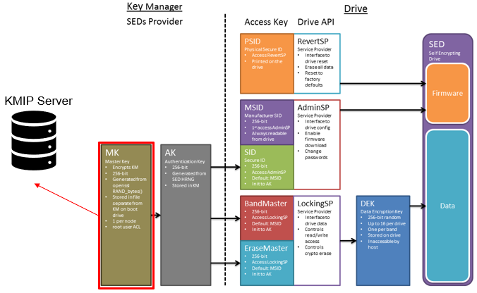
All data that is written to a DARE cluster is automatically encrypted the moment it is written and decrypted when it is read. The stored data is encrypted with a 256-bit data AES data encryption key (DEK), and OneFS controls data access by combining the drive authentication key (AK) with data-encryption keys.

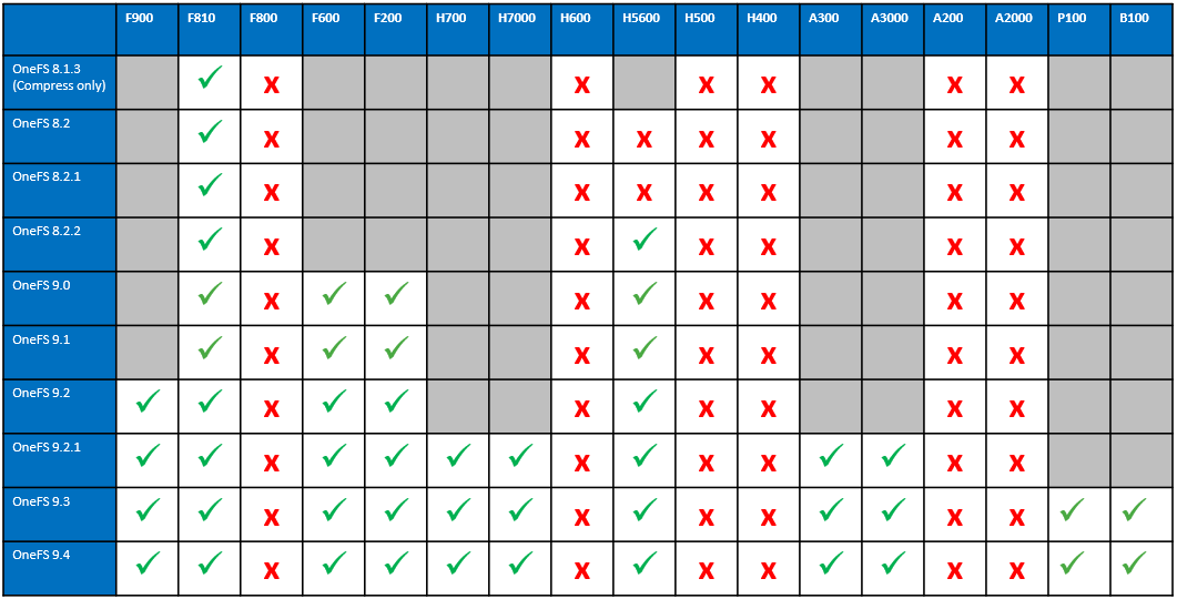
OneFS supports data-at-rest encryption using SEDs across all-flash SSD nodes, as well as HDD-based hybrid and archive platforms. However, all nodes in a DARE cluster must be of the self-encrypting drive type, and mixed SED and non-SED node clusters are not supported.

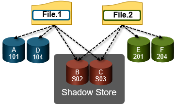
SEDs have the ability to be ‘locked’ or ‘unlocked’, over configurable ranges of logical block addresses (LBAs) known as ‘bands’. The bands on OneFS storage drives cover the /ifs and reserved partition, but leave a small amount at the beginning and end of the drive unlocked for the partition table. When OneFS formats a drive, isi_sed ‘takes ownership’ of it, which refers to us setting a password on the drive and storing it in the keystore. Similarly, ‘releasing ownership’ refers to resetting the drive back to a known password – the MSID, which is a password provided by the manufacturer, which can be read from the drive itself. Releasing ownership means that isi_sed will be able to use the MSID to authenticate to the drive and take ownership of it again if need be. It’s worth noting that changing these passwords changes the drive’s internal encryption key, and will scramble all data on the drives.

New PowerScale encryption nodes, and the SED drives they contain, initially arrive in an ‘unowned’, factory-fresh state, with encryption is disabled and no encryption keys present on the drives or node. On initialization, first a randomized internal drive encryption key is generated via the drive’s embedded encryption hardware. This key is used by the drive hardware to encrypt all incoming data before writing it to disk, and to decrypt any disk data being read by the node.

Next, a drive control key or drive access password is generated via the OneFS key manager process. This password is used each time the drive is accessed by the node. Without the password, the drive is completely inaccessible. With encryption now configured, the drive is in a secure, owned state and is ready to be formatted.

The data on self-encrypting drives is rendered inaccessible in the following conditions:

Event Description
Smartfail When a self-encrypting drive is smartfailed, drive authentication keys are deleted, making the drive unreadable. When you smartfail and then remove a drive, it is cryptographically erased. NOTE: Smartfailing a drive is the preferred method for removing a self-encrypting drive.
Power loss When a self-encrypting drive loses power, the drive locks to prevent unauthorized access. When power is restored, data is again accessible when the appropriate drive authentication key is provided.
Network loss When a cluster using external key management loses network connection to the external key management server, the drives are locked until the network connection is restored.
Password Loss If a SED drive’s internal key or drive access password is lost, the drive data is rendered permanently inaccessible, and the drive must be reset and reformatted in order to be repurposed.

If a SED drive is tampered with, say by interrupting the formatting process or removing the drive from a powered-on node for example, the node will automatically delete its drive access password from the keystore database where the drive access passwords are stored. If the internal drive key, drive access password, or both are lost or deleted, all of the data on the drive becomes permanently inaccessible and unreadable. This process is referred to as cryptographic erasure, as the data still exists, but can’t be decrypted. The drive is subsequently unusable, and it must be manually reverted to the unowned state by using its Physical Security ID (PSID). The PSID is a unique, static, 32-character key that is embedded in each drive at the factory. PSIDs are printed on the drive’s label, and can be retrieved only by physically removing the drive from the node and reading its label. After the PSID is entered in the OneFS command-line interface at the manual reversion prompt, all of the drive data is deleted and the SED drive is returned to an unowned state.

SEDs include a few additional isi_drive_d user states, as compared to regular drives.

SED State Description
SED_ERROR OneFS could not unlock or use the drive, typically because of a bad password or drive communication error.
ERASE The drive finished a smartfail, but OneFS was unable to release the drive, so just deleted its password.
INSECURE The drive isn’t owned by the node, but was unlocked and would have otherwise gone to ACTIVE.

Generally, these will only be reported in error cases. SEDs that are working properly and unlocked should behave like any other drives, and when running and in-use will show up as HEALTHY. That said, the most common error state is drives that show up as SED_ERROR. However, this just indicates that drive_d encountered anything other than SUCCESS or DRIVE_UNOWNED when attempting to unlock the drive.

To help debug a SED issue, determine if the drive is currently owned (non-MSID password), or unowned (default, MSID password) and test with the ‘isi_sed drivedisplay’ CLI command. If the drive is unowned, or the password does not work, you’ll likely need to PSID revert the drive.

Syntax Description
isi_sed drivedisplay <drive> Displays the drive’s current state of ownership. This is often the most directly helpful, since it should be obvious based on this whether error states are legitimate or not. If the command succeeds, you should be told either: drive is unowned, drive owned by this node, drive owned by another node.

·         ‘Drive owned by another node’ is the error case you can expect to see if we had a key and lost it, or you moved drives from node to node. This means the drive is locked and we don’t have a password – you’ll have to revert it or restore your lost passwords.

·         ‘Drive owned by this node’ is expected in most situations. – we have a

·         ‘Drive unowned’ can be either an error or unexpected case. Drives that are released or reverted should be in this state. Drives that have been formatted and are in-use should not. This means the drive is using the MSID (factory default) password.

isi_sed release <drive> Releases ownership of this drive. This will set the drive’s password back to the default, the drive’s MSID. This can be helpful for cases such as moving drives around – this will release a drive so that any other node/isi_sed can take ownership of the drive.
isi_sed revert <drive> This command is useful for lost passwords, etc. The revert operation will allow you to enter the PSID found on the drive, and with that reset the drive to a factory-fresh MSID-unlocked state. Another way to do this is to attempt an “isi dev -a format -d :[baynum of drive to revert]” – you will be prompted for the PSID, and drive_d will attempt to do the revert for you.

A healthy SED drive can easily be securely erased by simply Smartfailing the drive. Once the Smartfail process has completed, the node deletes the drive access password from the keystore and the drive deletes its internal encryption key. At this point, the data is inaccessible and is considered cryptographically erased, and the drive is reset back to its original ‘unowned’ state. The drive can then be reused once a new encryption key has been generated, or safely returned to Dell, without any risk of the vendor or a third party accessing the data.

In order to ensure that data on a SED is unreadable, during a successful Smartfail OneFS cryptographically erases data by changing the DEK and blocks read and write access to existing data by removing the access key. However, if the drive fails to respond during Smartfail and OneFS cannot perform cryptographic erasure, access to the drive’s data is still blocked by deleting the access key.

Smartfail State DEK erased and reset AK erased and reset Cryptographic erasure Data inaccessible
Replace Yes Yes Yes Yes
Erase Yes Yes

For a defective SED drive, the completion of the Smartfail process prompts the node to delete the drive access password from the keystore.

To erase all SED drives in a single node that is being removed from a cluster, smartfail the node from the cluster. All drives will be automatically released and cryptographically erased by the node when the smartfail process completes.

On completion of the Smartfail process, a node automatically reboots to the configuration wizard. The /var/log/isi_sed log log will contains a ‘release_ownership’ message for each drive as it goes through the Smartfail process, confirming it is in a ‘replace’ state. For example:

2022-05-25T22:45:56Z <1.6>H400-SED-4 isi_sed[46365]: Command: release_ownership, drive bays: 1

2022-06-25T22:46:39Z <1.6>H400-SED-4 isi_sed[46365]: Bay 1: Dev da1, HITACHI H5SMM328 CLAR800, SN 71V0G6SX, WWN 5000cca09c00d57f: release_ownership: Success

The following CLI command can be used cryptographically erase a SED by smartfailing the drive, in this case drive 10 on node 1:

# isi devices -a smartfail -d 1:10

The status of an ‘owned’ drive, in this case /dev/da10, is reported as such:

# isi_sed drive da10 -vDrive Status: Bay 10: WWN 5000c50056252af4Drive Model SEAGATE ST330006CLAR3000, SN 71V0G6SX 00009330KYE04Key      Key      MSID     Drive            DriveExists   Works    Works    State            Status=======  =======  =======  ===============  ===============Yes      Yes      No       OWNED            OWNEDDrive owned by nodeBay 10: Dev da10, SEAGATE ST330006CLAR3000, SN 71V0G6SX 00009330KYE04, WWN 5000c50056252af4: drive_display: Success

This drive can easily be ‘released’ as follows:

# isi_sed release da10 -vDrive Status: Before release_ownership (Restore drive to factory default state):Drive Status: Bay 10: WWN 5000c50056252af4Drive Model SEAGATE ST330006CLAR3000, SN 71V0G6SX 00009330KYE04Key      Key      MSID     Drive            DriveExists   Works    Works    State            Status=======  =======  =======  ===============  ===============Yes      Yes      No       OWNED            OWNEDDrive owned by nodeBay 10: Dev da10, SEAGATE ST330006CLAR3000, SN 71V0G6SX 00009330KYE04, WWN 5000c50056252af4: release_ownership: Success 

isi_sed drive da10 -v

Drive Status: Bay 10: WWN 5000c50056252af4

Drive Model SEAGATE ST330006CLAR3000, SN 71V0G6SX 00009330KYE04

Key      Key      MSID     Drive            Drive

Exists   Works    Works    State            Status

=======  =======  =======  ===============  ===============

No       No       Yes      UNOWNED          UNOWNED

Fresh unowned drive

Firmware Port Lock: Enabled, AutoLock: On Power Loss


              Auth Keys:               ReadLock   WriteLock  Auto   LBA       LBA

              MSID Curr Futr Chng Unkn Enb  Set   Enb  Set   Lock   Start     Size

============  ======================== ========== ========== =====  ========= =========

SID           Y    --   --   --

EraseMaster   Y    --   --   --

BandMaster0   Y    --   --   --        N    N     N    N     N      0         0

BandMaster1   Y    --   --   --        N    N     N    N     N      0         0

BandMaster2   Y    --   --   --        N    N     N    N     N      0         0

BandMaster3   Band Disabled

BandMaster4   Band Disabled

BandMaster5   Band Disabled

BandMaster6   Band Disabled

BandMaster7   Band Disabled

BandMaster8   Band Disabled

BandMaster9   Band Disabled

BandMaster10  Band Disabled

BandMaster11  Band Disabled

BandMaster12  Band Disabled

BandMaster13  Band Disabled

BandMaster14  Band Disabled

Bay 10: Dev da10, SEAGATE ST330006CLAR3000, SN 71V0G6SX 00009330KYE04, WWN 5000c50056252af4: drive_display: Success

Similarly, all of the SEDs in a node can be erased by Smartfailing the entire node, in this case node 2:

# isi devices -a smartfail -d <node>

The ‘isi_reformat_node’ CLI tool can be used to either reimage or reformat a single node or entire cluster, thereby erase all its SED drives. Either a reformat or reimage will first ‘release’ the drives and then delete the node keystore. Plus, even if a drive fails to properly release, it will still be cryptographically erased since its drive access passwords is deleted along with the rest of the keystore during the process. However, note that any SED drives in nodes destined for redeployment elsewhere and which are currently in an unreleased state must be manually reverted by using their PSID before they can be used again.

# isi_reformat_node

The node will be automatically formatted. To erase all of the SEDs in an entire cluster, log in to each individual node as root and issue the above ‘isi_reformat_node’ command.

A drive that has been cryptographically erased can be verified as follow. First, use the ‘isi_drivenum’ CLI command to display the device names of the cluster’s drives. For example:
# isi_drivenum

Bay  1   Unit 0      Lnum 30    Active      SN:9VNX0JA02433     /dev/da1

Bay  2   Unit N/A    Lnum N/A   N/A         SN:N/A              N/A

Bay  A0   Unit 13     Lnum 17    Active      SN:0BHHH2TF         /dev/da14

Bay  A1   Unit 29     Lnum 1     Active      SN:0BHHHJRF         /dev/da30

Bay  A2   Unit 1      Lnum 29    Active      SN:0BHHH73F         /dev/da2

Bay  A3   Unit 16     Lnum 14    Active      SN:0BHHDL6F         /dev/da17

Bay  A4   Unit 2      Lnum 28    Active      SN:0BHHH7VF         /dev/da3

Bay  A5   Unit 17     Lnum 13    Active      SN:0BHHDYNF         /dev/da18

Bay  B0   Unit 30     Lnum 0     Active      SN:0BHKUBNH         /dev/da31

Bay  B1   Unit 14     Lnum 16    Active      SN:0BHHEBVF         /dev/da15

Bay  B2   Unit 18     Lnum 12    Active      SN:0BHDH7JF         /dev/da19

Bay  B3   Unit 3      Lnum 27    Active      SN:0BHHE6VF         /dev/da4

Bay  B4   Unit 19     Lnum 11    Active      SN:0BHDH9VF         /dev/da20

Bay  B5   Unit 4      Lnum 26    Active      SN:0BHHEEEF         /dev/da5

Bay  C0   Unit 15     Lnum 15    Active      SN:0BHHDLMF         /dev/da16

Bay  C1   Unit 26     Lnum 4     Active      SN:0BHHDNUF         /dev/da27

Bay  C2   Unit 5      Lnum 25    Active      SN:0BHHDL2F         /dev/da6

Bay  C3   Unit 20     Lnum 10    Active      SN:0BHHDKTF         /dev/da21

Bay  C4   Unit 6      Lnum 24    Active      SN:0BHHHGVF         /dev/da7

Bay  C5   Unit 21     Lnum 9     Active      SN:0BHHH4XF         /dev/da22

Bay  D0   Unit 27     Lnum 3     Active      SN:0BHHDKYF         /dev/da28

Bay  D1   Unit 11     Lnum 19    Active      SN:0BHHH9EF         /dev/da12

Bay  D2   Unit 22     Lnum 8     Active      SN:0BHHDL4F         /dev/da23

Bay  D3   Unit 7      Lnum 23    Active      SN:0BHHDWEF         /dev/da8

Bay  D4   Unit 23     Lnum 7     Active      SN:0BHHDSXF         /dev/da24

Bay  D5   Unit 8      Lnum 22    Active      SN:0BHHDKVF         /dev/da9

Bay  E0   Unit 12     Lnum 18    Active      SN:0BHHH9PF         /dev/da13

Bay  E1   Unit 28     Lnum 2     Active      SN:0BHHHGEF         /dev/da29

Bay  E2   Unit 9      Lnum 21    Active      SN:0BHHHAAF         /dev/da10

Bay  E3   Unit 24     Lnum 6     Active      SN:0BHHE06F         /dev/da25

Bay  E4   Unit 10     Lnum 20    Active      SN:0BHHDZTF         /dev/da11

Bay  E5   Unit 25     Lnum 5     Active      SN:0BHHDRBF         /dev/da26

Note that the drive device names are displayed in the format ‘/dev/da#’, where ‘#’ is a number. Only the ‘da#’ portion is needed for the isi_sed CLI syntax.

For example, to query the state of SED drive ‘da10’:

# isi_sed drive da10

Note that this command may take 30 seconds or longer to complete.

Finally, the data on the drive has been cryptographically erased if the ‘Drive State’ and ‘Drive Status’ columns display a status of UNOWNED, and ‘Fresh unowned drive’ appears in the line below the table. The drive has been reset and its internal encryption key has been destroyed, cryptographically erasing the drive. For example:

# isi_sed drive da10

Drive Status: Bay 10: WWN 5000c50056252af4

Drive Model SEAGATE ST330006CLAR3000, SN 71V0G6SX 00009330KYE04

Key      Key      MSID     Drive            Drive

Exists   Works    Works    State            Status

=======  =======  =======  ===============  ===============

No       No       Yes      UNOWNED          UNOWNED

Fresh unowned drive

Bay 10: Dev da10, SEAGATE ST330006CLAR3000, SN 71V0G6SX 00009330KYE04, WWN 5000c50056252af4: drive_display: Success

If the Drive State and Drive Status columns display a status of AUTH FAILED, this indicates that the drive password (AK) is no longer present in the node keystore. For example:

# isi_sed drive da10

Drive Status: Bay 10: WWN 5000c50056252af4

Drive Model SEAGATE ST330006CLAR3000, SN 71V0G6SX 00009330KYE04

Key      Key      MSID     Drive            Drive

Exists   Works    Works    State            Status

=======  =======  =======  ===============  ===============

No       No       Yes      AUTH FAILED      AUTH FAILED

Since the password is not stored anywhere else, the drive is now inaccessible until it is manually reverted.

If a drive is removed from a running node, OneFS automatically assumes that the drive has failed, and initiates the Smartfail process. If the drive is reinserted before the smartfail process completes, the ‘add’ and ‘stopfail’ commands can be run manually in order to bring the drive back online and return it to a healthy state. However, if the smartfail process has completed before reinserting the drive, running the stopfail command will be ineffective since the drive access password for the removed drive is deleted from the node’s keystore and is considered cryptographically erased.

However, if the drive is reinserted and added back to the cluster after it has been smartfailed, OneFS will report it as being in the SED_ERROR state because the drive still contains encrypted data but the drive access password no longer exists in the node’s keystore. Although the data on the drive is inaccessible, the drive can be reverted to an unowned state by using its PSID. At this point, the drive can then be reused.

When necessary, a SED drive can be cryptographically erased and reset to a factory-fresh state, either by issuing it the ‘release_ownership’ command, or by sending the ‘revert_factory_default’ command. For example, using drive /dev/da10:

# isi_sed release_ownership da10

Or:

# isi_sed revert_factory_default da10

The release command requires the drive password in order to run, whereas the revert command requires the drive physical PSID. If the drive password is still known and functional, the node can release the drive after the smartfail process completes, or during a node reimage, without requiring manual intervention. If the drive password is lost or no longer functional, the revert command must be used instead, and the PSID must be entered manually.

If a SED drive becomes inaccessible for any reason, such as mishandling, malfunction, intentional or accidental release/revert, or loss of the data access password, the drive data cannot be retrieved. Traditional data recovery techniques, such as direct media access and platter extraction, are ineffective on a SED drive since the data is encrypted, and the encryption key cannot be extracted from the drive hardware.

Performance-wise, there is no significant difference in read or write performance between SED and non-SED drives. All data encryption and decryption is done at line speed by dedicated AES encryption hardware that is embedded in the drive.

Format times for SED nodes may vary, but 90 minutes or more is the average for most 4TB SED nodes. The larger the drives, the longer the format process will take to complete. SED nodes take much longer to format than nodes with regular drives, because each drive must be fully overwritten with random data as part of the encryption initialization process. This is an industry-standard step in all full-disk encryption processes that is necessary to help secure the encrypted data against brute-force attacks on the encryption key, and this step cannot be skipped.

OneFS provides drive formatting progress information, which is displayed as a completion percentage for each drive.

It is important to avoid interrupting a formatting process on a SED node. Inadvertently doing so will immediately make all the drives in the node unusable, necessitating a manual revert for each individual drive using its PSID, before the format process can be restarted.

# isi_sed revert /dev/da1

Bear in mind that this can be a somewhat cumbersome process, which can take several hours.

OneFS Cbind and DNS Caching

OneFS cbind is the distributed DNS cache daemon for a PowerScale cluster. As such, its primary role is to accelerate domain name lookups on the cluster, particularly for NFS workloads, which can frequently involve a large number of lookups requests, especially when using netgroups. Cbind itself is logically separated into two halves:

Component Description
Gateway cache The entries a node refreshes from the DNS server.
Local cache The entries a node refreshes from the Gateway node.

Cbind’s architecture helps to distribute the cache and associated DNS workload across all nodes in the cluster, and the daemon runs as a OneFS service under the purview of MCP and the /etc/mcp/sys/services/isi_cbind_d control script:

# isi services -a | grep i bind

   isi_cbind_d          Bind Cache Daemon                        Enabled

On startup the cbind daemon, isi_cbind_d, reads its configuration from the cbind_config.gc gconfig file. If needed, configuration changes can be made using the ‘isi network dnscache’ or ‘isi_cbind’ CLI tools.

The cbind daemon also supports multi-tenancy across the cluster, with each tenant’s groupnet being allocated its own completely independent DNS cache, with multiple client interfaces to separate DNS requests from different groupnets. Cbind uses the 127.42.x.x address range and can be accessed by client applications across the entire range. The lower 16 bytes of the address are set by the client to the groupnet ID for the query. For example, if the client is trying to query the DNS servers on groupnet with ID 5 it will send the DNS query to 127.42.0.5.

Under the hood, the cbind daemon comprises two DNS query/response containers, or ‘stallsets’:

Component Description
DNS stallset The DNS stallset is a collection of DNS stalls which encapsulate a single DNS server and a list of DNS queries which have been sent to the DNS servers and are waiting for a response.
Cluster stallset The cluster stallset is similar to the DNS stallset, except the cluster stalls encapsulate the connection to another node in the cluster, known as the gateway node. It also holds a list of DNS queries which have been forwarded to the gateway node and are waiting for a response.

Contained within a stallset are the stalls themselves, which store the actual DNS requests and responses. The DNS stallset provides a separate stall for each DNS server that cbind has been configured to use, and requests are handled via a round-robin algorithm. Similarly, for the cluster stallset, there is a stall for each node within the cluster. The index of the cluster stallset is the gateway node’s (devid – 1).

The cluster stallset entry for the node that is running the daemon is treated as a special case, known as ‘L1 mode’, because the gateway for these DNS requests is the node executing the code. Requests on the gateway stall also have an entry on the DNS stallset representing the request to the external DNS server. All other actively participating cluster stallset entries are referred to as ‘L2+L1’ mode. However, if a node cannot reach DNS, it is moved to L2 mode to prevent it from being used by the other nodes. An associated log entry is written to /var/log/isi_cbind_d.log, of the form:

isi_cbind_d[6204]: [0x800703800]bind: Error

sending query to dns:10.21.25.11: Host is down

In order to support large clusters, cbind uses a consistent hash to determine the gateway node to cache a request and the appropriate cluster stallset to use. This consistent hashing algorithm, which decides on which node to cache an entry, is designed to minimize the number of entry transfers as nodes are added/removed, while also reducing the number of threads and UDP ports used. To illustrate cbind’s consistent hashing, consider the following three node cluster:

In this scenario, when the cbind service on Node 3 becomes active, one third each of the gateway cache from node 1 and 2 respectively gets transferred to node 3. Similarly, if node 3’s cbind service goes down, its gateway cache is divided equally between nodes 1 and 2. For a DNS request on node 3, the node first checks its local cache. If the entry is not found, it will automatically query the gateway (for example, node 2). This means that even if node 3 cannot talk to the DNS server directly, it can still cache the entries from a different node.

So, upon startup, a node’s cbind process attempts to contact, or ‘ping’, the DNS servers. Once a reply is received, the cbind moves into an up state and notifies GMP that the isi_cbind_d service is running on this node. GMP, in turn, then informs the cbind processes across the rest of the cluster that the node is up and available.

Conversely, after several DNS requests to an external server fail for a given node or the isi_cbind_d process is terminated, then the GMP code is notified that the isi_cbind_d service is down for this node. GMP then notifies the cluster that the node is down. When a cbind process (on node Y) receives this notification, the consistent hash algorithm is updated to report that node X is down. The cluster stallset is not informed of this change. Instead the DNS requests that have changed gateways will eventually timeout and be deleted.

As such, the cbind request and response processes can be summarized as follows:

  1. A client on the node sends a DNS query on the additional loopback address 127.42.x.x which is received by cbind.
  2. The cbind daemon uses the consistent hash algorithm to calculate the gateway value of the DNS query and uses the gateway to index the cluster stallset.
  3. If there is a cache hit, a response is sent to the client and the transaction is complete.
  4. Otherwise, the DNS query is placed in the cluster stallset using the gateway as the index. If this is the gateway node then the request is sent to the external DNS server, otherwise the DNS request is forwarded to the gateway node.
  5. When the DNS server or gateway replies, another thread receives the DNS response and matches it to the query on the list. The response is forwarded to the client and the cluster stallset is updated.

Similarly, when a request is forwarded to the gateway node:

  1. The cbind daemon receives the request, calculates the gateway value of the DNS query using the consistent hash algorithm, and uses the gateway to index the cluster stallset.
  2. If there is a cache hit, a response is returned to the remote cbind process and the transaction is complete.
  3. Otherwise, the DNS query is placed in the cluster stallset using the gateway as the index and the request is sent to the external DNS server.
  4. When the DNS server or gateway returns, another thread receives the DNS response and matches it to the query on the list. The response is forwarded to the calling node and the cluster stallset is updated.

If necessary, cbind DNS caching can be enabled or disabled via the ‘isi network groupnets’ command set, allowing the cache to be managed per groupnet:

# isi network groupnets modify --id=<groupnet-name> --dns-cache-enabled=<true/false>

The global ‘isi network dnscache’ command set can be useful for inspecting the cache configuration and limits:

# isi network dnscache view

Cache Entry Limit: 65536

  Cluster Timeout: 5

      DNS Timeout: 5

    Eager Refresh: 0

   Testping Delta: 30

  TTL Max Noerror: 3600

  TTL Min Noerror: 30

 TTL Max Nxdomain: 3600

 TTL Min Nxdomain: 15

    TTL Max Other: 60

    TTL Min Other: 0

 TTL Max Servfail: 3600

 TTL Min Servfail: 300

 The following table describes these DNS cache parameters, which can be manually configured if desired.

Setting Description
TTL No Error Minimum Specifies the lower boundary on time-to-live for cache hits (default value=30s).
TTL No Error Maximum Specifies the upper boundary on time-to-live for cache hits (default value=3600s).
TTL Non-existent Domain Minimum Specifies the lower boundary on time-to-live for nxdomain (default value=15s).
TTL Non-existent Domain Maximum Specifies the upper boundary on time-to-live for nxdomain (default value=3600s).
TTL Other Failures Minimum Specifies the lower boundary on time-to-live for non-nxdomain failures (default value=0s).
TTL Other Failures Maximum Specifies the upper boundary on time-to-live for non-nxdomain failures (default value=60s).
TTL Lower Limit For Server Failures Specifies the lower boundary on time-to-live for DNS server failures(default value=300s).
TTL Upper Limit For Server Failures Specifies the upper boundary on time-to-live for DNS server failures (default value=3600s).
Eager Refresh Specifies the lead time to refresh cache entries that are nearing expiration (default value=0s).
Cache Entry Limit Specifies the maximum number of entries that the DNS cache can contain (default value=35536 entries).
Test Ping Delta Specifies the delta for checking the cbind cluster health (default value=30s).

 Also, if necessary, the cache can be globally flushed via the following CLI syntax:

# isi network dnscache flush -v

Flush complete.

OneFS also provides the ‘isi_cbind’ CLI utility, which can be used to communicate with the cbind daemon. This utility supports both regular CLI syntax, plus an interactive mode where commands are   prompted for. Interactive mode can be entered by invoking the utility without an argument, for example:

# isi_cbind

cbind:

cbind: quit

#

The following command options are available:

# isi_cbind help

        clear           - clear server statistics

        dump            - dump internal server state

        exit            - exit interactive mode

        flush           - flush cache

        quit            - exit interactive mode

        set             - change volatile settings

        show            - show server settings or statistics

        shutdown        - orderly server shutdown

An individual groupnet’s cache can be flushed as follows, in this case targeting the ‘client1’ groupnet:

# isi_cbind flush groupnet client1

Flush complete.

Note that all the cache settings are global and, as such, will affect all groupnet DNS caches.

The cache statistics are available via the following CLI syntax, for example:

# isi_cbind show cache

  Cache:

    entries:                 10         - entries installed in the cache

    max_entries:            338         - entries allocated, including for I/O and free list

    expired:                  0         - entries that reached TTL and were removed from the cache

    probes:                 508         - count of attempts to match an entry in the cache

    hits:                   498 (98%)   - count of times that a match was found

    updates:                  0         - entries in the cache replaced with a new reply

    response_time:     0.000005         - average turnaround time for cache hits

These cache stats can be cleared as follows:

# isi_cbind clear cache

Similarly, the DNS statistics can be viewed with the ‘show dns’ argument:

# isi_cbind show dns

  DNS server 1: (dns:10.21.25.10)

    queries:                862         - queries sent to this DNS server

    responses:              862 (100%)  - responses that matched a pending query

    spurious:             17315 (2008%) - responses that did not match a pending query

    dropped:              17315 (2008%) - responses not installed into the cache (error)

    timeouts:                 0 (  0%)  - times no response was received in time

    response_time:     0.001917         - average turnaround time from request to reply

  DNS server 2: (dns:10.21.25.11)

    queries:                861         - queries sent to this DNS server

    responses:              860 ( 99%)  - responses that matched a pending query

    spurious:             17314 (2010%) - responses that did not match a pending query

    dropped:              17314 (2010%) - responses not installed into the cache (error)

    timeouts:                 1 (  0%)  - times no response was received in time

    response_time:     0.001603         - average turnaround time from request to reply


When running isi_cbind_d, the following additional options are available, and can be invoked with the following CLI flags and syntax:

Option Flag Description
Debug -d Set debug flag(s) to log specific components.  The flags are comma separated list from the following components:

all     Log all components.

cache   Log information relating to cache data.

cluster  Log information relating to cluster data.

flow    Log information relating to flow data.

lock    Log information relating to lock data.

link    Log information relating to link data.

memory  Log information relating to memory data.

network  Log information relating to network data.

refcount  Log information relating to cache object refcount data.

timing  Log information relating to cache timing data.

external   Special debug option to provide off-node DNS service.

Output -f Isi_cbind will not detach from the controlling terminal and will print debugging messages to stderr.
Dump to -D Target file for isi_cbind dump output.
Port -p Uses specified port instead of default NS port of 53.

The isi_cbind_d process logs messages to syslog or to stderr, depending on the daemon’s mode. The log level can be changed by sending it a SIGUSR2 signal, which will toggle the debug flag to maximum or back to the original setting. For example:

# kill -USR2 `cat /var/run/isi_cbind_d.pid`

Also, when troubleshooting cbind, the following files can provide useful information:

File Description
/var/run/isi_cbind_d.pid the pid of the currently running process
/var/crash/isi_cbind_d.dump output file for internal state and statistics
/var/log/isi_cbind_d.log syslog output file
/etc/gconfig/cbind_config.gc configuration file
/etc/resolv.conf bind resolver configuration file

Additionally, the internal state data of isi_cbind_d can be dumped to a file specified with the -D option, described in the table above.

Astute observers will also notice the presence of an additional loopback address at 127.42.0.1:

0: flags=8049<UP,LOOPBACK,RUNNING,MULTICAST> metric 0 mtu 16384
        options=680003<RXCSUM,TXCSUM,LINKSTATE,RXCSUM_IPV6,TXCSUM_IPV6>
        inet6 ::1 prefixlen 128 zone 1
        inet6 fe80::1%lo0 prefixlen 64 scopeid 0x4 zone 1
        inet 127.0.0.1 netmask 0xff000000 zone 1
        inet 127.42.0.1 netmask 0xffff0000 zone 1
        groups: lo
        nd6 options=21<PERFORMNUD,AUTO_LINKLOCAL>
# grep 127 /etc/resolv.conf
nameserver 127.42.0.1
# sockstat | grep "127.42.0.1:53"

root     isi_cbind_ 4078  7  udp4   127.42.0.1:53         *:*

This entry is used to ensure that outbound DNS queries are intercepted by cbind, which then either utilizes its cache or reaches out to the DNS servers based on the groupnet configuration. The standard outbound uses the default groupnet, and Auth is forwarded to the appropriate groupnet DNS.

OneFS NANON

Another functionality enhancement that debuts in the OneFS 9.4 release is increased support for clusters with partial front-end connectivity. In OneFS parlance, these are known as NANON clusters, the acronym abbreviating ‘Not All Nodes On Network’. Today, every PowerScale node in the portfolio includes both front-end and back-end network interfaces. Both of a node’s redundant backend network ports, either Ethernet or Infiniband, must be active and connected to the supplied cluster switches at all times, since these form a distributed systems bus and handle all the intra-cluster communication. However, while the typical cluster topology has all nodes connected to all the frontend client network(s), this is not always possible or even desirable. In certain scenarios, there are distinct benefits to not connecting all the nodes to the front-end network.

But first, some background. Imagine an active archive workload, for example. The I/O and capacity requirements of the workload’s active component can be satisfied by an all-flash F600 pool. In contrast, the inactive archive data is housed on a pool of capacity-optimized A3000 nodes for archiving inactive data. In this case, not connecting the A3000 nodes to the front-end network saves on switch ports, isolates the archive data pool from client I/O, and simplifies the overall configuration, while also potentially increasing security.

Such NANON cluster configurations are increasing in popularity, as customers elect not to connect the archive nodes in larger clusters to save cost and complexity, reduce load on capacity optimized platforms, as well as creating physically secure and air-gapped solutions. The recent introduction of the PowerScale P100 and B100 accelerator nodes also increase a cluster’s front end connectivity flexibility.

The above NANON configuration is among the simplest of the partially connected cluster architectures. In this example, the deployment consists of five PowerScale nodes with only three of them connected to the network. The network is assumed to have full access to all necessary infrastructure services and client access.

More complex topologies can often include separating client and management networks, dedicated replication networks, multi-tenant and other separated front-end solutions, and often fall into the NANOAN, or Not All Nodes On All Networks, category. For example:

The management network can be assigned to Subnet0 on the cluster nodes, with a gateway priority of 10 (ie. default gateway), and the client network using Subnet1 with a gateway priority of 20. This would route all outbound traffic through the management network. Static Routes, or Source-Based Routing (SBR) can be configured to direct traffic to the appropriate gateway if issues arise with client traffic routing through the management network.

In this replication topology, nodes 1 through 3 on the source cluster are used for client connectivity, while nodes 4 and 5 on both the source and target clusters are dedicated for SyncIQ replication traffic.

Other more complex examples, such multi-tenant cluster topologies, can be deployed to support workloads requiring connectivity to multiple physical networks.

The above topology can be configured with a management Groupnet containing Subnet0, and additional Groupnets, each with a subnet, for the client networks. For example:

# isi network groupnets list

ID         DNS Cache Enabled  DNS Search      DNS Servers   Subnets

--------------------------------------------------------------------

Client1    1                  c1.isilon.com   10.231.253.14 subnet1

Client2    1                  c2.isilon.com   10.231.254.14 subnet2

Client3    1                  c3.isilon.com   10.231.255.14 subnet3

Management 1                  mgt.isilon.com  10.231.252.14 subnet0

--------------------------------------------------------------------

Total: 4

Or from the WebUI via Cluster management > Network configuration > External network

The connectivity details of a particular subnet and pool and be queried with the ‘isi network pools status <groupnet.subnet.pool>’ CLI command, and will provide details of node connectivity, as well as protocol health and general node state. For example, querying the management groupnet  (Management.Subnet0.Pool0) for the six node cluster above, we see that nodes 1-4 are externally connected, whereas nodes 5 and 6 are not:

# isi network pools status Management.subnet0.pool0

Pool ID: Management.subnet0.subnet0

SmartConnect DNS Overview:

       Resolvable: 4/6 nodes resolvable

Needing Attention: 2/6 nodes need attention

        SC Subnet: Management.subnet0


Nodes Needing Attention:

              LNN: 5

SC DNS Resolvable: False

       Node State: Up

        IP Status: Doesn't have any usable IPs

 Interface Status: 0/1 interfaces usable

Protocols Running: True

        Suspended: False

--------------------------------------------------------------------------------

              LNN: 6

SC DNS Resolvable: False

       Node State: Up

        IP Status: Doesn't have any usable IPs

 Interface Status: 0/1 interfaces usable

Protocols Running: True

        Suspended: False

There are two core OneFS components that have been enhanced in 9.4 in order to better support NANON configurations on a cluster. These are:

Name Component Description
Group Management GMP_SERCVICE_

EXT_CONNECTIVE

Allows GMP (Group Management Protocol) to report the cluster nodes’ external connectivity status.
MCP process isi_mcp Monitors for any GMP changes and, when detected, will try to start or stop the affected service(s) under its control.
SmartConnect isi_smartconnect_d Cluster’s network configuration and connection management service. If the SmartConnect daemon decides a node is NANON, OneFS will log the cluster’s status with GMP.

Here’s the basic architecture and inter-relation of the services.

The GMP external connectivity status is available via the ‘sysctl efs.gmp.group’ CLI command output.

For example, take a three node cluster with all nodes’ front-end interfaces connected:

GMP confirms that all three nodes are available, as indicated by the new ‘external_connectivity’ field:

# sysctl efs.gmp.group

efs.gmp.group: <79c9d1> (3) :{ 1-3:0-5, all_enabled_protocols: 1-3, isi_cbind_d: 1-3, lsass: 1-3, external_connectivity: 1-3 }

This new external connectivity status is also incorporated into a new ‘Ext’ column in the ‘isi status’ CLI command output, as indicated by a ‘C’ for connected or an ‘N’ for not connected. For example:

# isi status -q

                   Health Ext  Throughput (bps)  HDD Storage      SSD Storage

ID |IP Address     |DASR |C/N|  In   Out  Total| Used / Size     |Used / Size

---+---------------+-----+---+-----+-----+-----+-----------------+-----------

  1|10.219.64.11   | OK  | C |25.9M| 2.1M|28.0M|(10.2T/23.2T(44%)|

  2|10.219.64.12   | OK  | C | 840K| 123M| 124M|(10.2T/23.2T(44%)|

  3|10.219.64.13   | OK  | C |    225M| 466M| 691M|(10.2T/23.2T(44%)|

---+---------------+-----+---+-----+-----+-----+-----------------+-----------

Cluster Totals:              |  n/a|  n/a|  n/a|30.6T/69.6T( 37%)|

     Health Fields: D = Down, A = Attention, S = Smartfailed, R = Read-Only

           External Network Fields: C = Connected, N = Not Connected

Take the following three node NANON cluster:

GMP confirms that only nodes 1 and 3 are connected to the front-end network. Similarly, the absence of node 2 from the command output infers that this node has no external connectivity:

# sysctl efs.gmp.group

efs.gmp.group: <79c9d1> (3) :{ 1-3:0-5, all_enabled_protocols: 1,3, isi_cbind_d: 1,3, lsass: 1,3, external_connectivity: 1,3 }

Similarly, the ‘isi status’ CLI output reports that node 2 is not connected, denoted by an ‘N’, in the ‘Ext’ column:

# isi status -q

                   Health Ext  Throughput (bps)  HDD Storage      SSD Storage

ID |IP Address     |DASR |C/N|  In   Out  Total| Used / Size     |Used / Size

---+---------------+-----+---+-----+-----+-----+-----------------+-----------

  1|10.219.64.11   | OK  | C | 9.9M| 12.1M|22.0M|(10.2T/23.2T(44%)|

  2|10.219.64.12   | OK  | N |    0|    0|    0|(10.2T/23.2T(44%)|

  3|10.219.64.13   | OK  | C | 440M| 221M| 661M|(10.2T/23.2T(44%)|

---+---------------+-----+---+-----+-----+-----+-----------------+-----------

Cluster Totals:              |  n/a|  n/a|  n/a|30.6T/69.6T( 37%)|

     Health Fields: D = Down, A = Attention, S = Smartfailed, R = Read-Only

           External Network Fields: C = Connected, N = Not Connected

Under the hood, OneFS 9.4 sees the addition of a new SmartConnect network module to evaluate and determine if the node has front-end network connectivity. This module leverages the GMP_SERVICE_EXT_CONNECTIVITY service and polls the nodes network settings every five minutes by default. SmartConnect’s evaluation and assessment criteria for network connectivity is as follows:

VLAN VLAN IP Interface Interface IP NIC Network
(any) (any) Up No Up No
(any) (any) Up Yes Up Yes
Enabled Yes (any) (any) Up Yes
(any) (any) (any) (any) Down No

OneFS 9.4 also adds an option to MCP, the master control process, which allows it to prevent certain services from being started if there is no external network. As such, the two services in 9.4 that now fall under MCP’s new NANON purview are:

Service Daemon Description
Audit isi_audit_cee Auditing of system configuration and protocol access events on the cluster.
SRS isi_esrs_d Allows remote cluster monitoring and support through Secure Remote Services (SRS).

There are two new MCP configuration tags, introduced to control services execution depending on external network connectivity:

Tag Description
require-ext-network Delay start of service if no external network connectivity.
stop-on-ext-network-loss Halt service if external network connectivity is lost.

These tags are used in the MCP service control scripts, located under /etc/mcp/sys/services. For example, in the SRS script:

# cat /etc/mcp/sys/services/isi_esrs_d

<?xml version="1.0"?>

<service name="isi_esrs_d" enable="0" display="1" ignore="0" options="require-quorum,stop-on-ext-network-loss">

      <isi-meta-tag id="isi_esrs_d">

            <mod-attribs>enable ignore display</mod-attribs>

      </isi-meta-tag>

      <description>ESRS Service Daemon</description>

      <process name="isi_esrs_d" pidfile="/var/run/isi_esrs_d.pid"

               startaction="start" stopaction="stop"

               depends="isi_tardis_d/isi_tardis_d"/>

      <actionlist name="start">

            <action>/usr/bin/isi_run -z 1 /usr/bin/isi_esrs_d</action>

      </actionlist>

      <actionlist name="stop">

            <action>/bin/pkill -F /var/run/isi_esrs_d.pid</action>

      </actionlist>

</service>

This MCP NANON control will be expanded to additional OneFS services over the course of subsequent releases.

When it comes to troubleshooting NANON configurations, the MCP, SmartConnect and general syslog log files can provide valuable connectivity troubleshooting messages and timestamps,. The pertinent logfiles are:

  • /var/log/messages
  • /var/log/isi_mcp
  • /var/log/isi_smartconnect

OneFS SmartConnect Diagnostics

SmartConnect, OneFS’ front-end load balancer and connection broker, is a bastion of the cluster that is intrinsically linked into many different areas of the product. Prior to OneFS 9.4, investigating the underlying cause of SmartConnect node resolution and/or connectivity issues typically required a variety of CLI tools and varied output, often making troubleshooting an unnecessarily cumbersome process.

With the addition of SmartConnect diagnostics, the initial troubleshooting process in OneFS 9.4 is now distilled down into a single ‘isi network pool status’ CLI command.

Issue OneFS 9.3 and Earlier Commands OneFS 9.4 Command
Node down isi stat  or  sysctl efs.gmp.group isi network pool status
Node smart-failing isi stat  or  sysctl efs.gmp.group isi network pool status
Node shutdown read-only isi stat  or  sysctl efs.gmp.group isi network pool status
Node rebooting sysctl efs.gmp.group isi network pool status
Node draining sysctl efs.gmp.group isi network pool status
Required protocols not running sysctl efs.gmp.group isi network pool status
Node suspended in network pool isi network pool view isi network pool status
Node interfaces down isi network interfaces list isi network pool status
Node missing IPs isi network interfaces list isi network pool status
Node IPs about to move No easy way to check isi network pool status

As the table above shows, this new diagnostic information source provides a single interface to view the primary causes affecting a node’s connectivity. For any given network pool, a summary of nodes and how many of them are resolvable is returned. Additionally, for each non-resolvable node, the detailed status is reported so the root cause can be pinpointed, providing enough context to narrow the scope of investigation to the correct component(s).

Specifically, the ‘isi network pool status’ CLI command in 9.4 now reports on the following attributes, making SmartConnect considerably easier to troubleshoot:

Attribute Possible Values
SC DNS Resolvable ·         True

·         False

Node State ·         Up

·         Draining

·         Smartfailing

·         Shutting Down

·         Down

IP Status ·         Has usable IPs

·         Does not have usable IPs

·         Does not have any configured IPs

Interface Status ·         x/y interfaces usable
Protocols Running ·         True

·         False

Suspended ·         True

·         False

Note that, while no additional configuration is needed, the ISI_PRIV_NETWORK privileges are required on a cluster account in order to run this CLI command.

In the following example, the CLI output clearly indicates that node 3 is down and requires attention. As such, it has no usable interfaces or IPs, no protocols running, and is not resolvable via SmartConnect DNS:

# isi network pool status subnet0.pool0 --show-all

Pool ID: groupnet0.subnet0.pool0


SmartConnect DNS Overview:

       Resolvable: 2/3 nodes resolvable

Needing Attention: 1/3 nodes need attention

        SC Subnet: groupnet0.subnet0


Nodes:

              LNN: 1

SC DNS Resolvable: True

       Node State: Up

        IP Status: Has usable IPs

 Interface Status: 1/1 interfaces usable

Protocols Running: True

        Suspended: False

-----------------------------------------------------------------------

              LNN: 2

SC DNS Resolvable: True

       Node State: Up

        IP Status: Has usable IPs

 Interface Status: 1/1 interfaces usable

Protocols Running: True

        Suspended: False

-----------------------------------------------------------------------

              LNN: 3

SC DNS Resolvable: False

       Node State: Down

        IP Status: Doesn't have any usable IPs

 Interface Status: 0/1 interfaces usable

Protocols Running: False

        Suspended: False

-----------------------------------------------------------------------

While currently, this new diagnostic information in OneFS 9.4 is only available via the CLI, it will be added to the WebUI in a future release..

OneFS Healthcheck Auto-updates

Prior to OneFS 9.4, Healthchecks were frequently regarded by storage administrators as yet another patch that need to be installed on a PowerScale cluster. As a result, their adoption was routinely postponed or ignored, potentially jeopardizing a cluster’s wellbeing. To address this, OneFS 9.4 introduces Healthcheck auto-updates, enabling new Healthchecks to be automatically downloaded and non-disruptively installed on a PowerScale cluster without any user intervention.

This new automated Healthcheck update framework helps accelerate the adoption of OneFS Healthchecks, by removing the need for manual checks, downloads and installation. In addition to reducing management overhead, the automated Healthchecks integrate with CloudIQ to update the cluster health score – further improving operational efficiency, while avoiding known issues affecting cluster availability.

Formerly known as Healthcheck patches, with OneFS 9.4 these are now renamed as Healthcheck definitions. The Healthcheck framework checks for updates to these definitions via Dell Secure Remote Services (SRS).

An auto-update configuration setting in the OneFS SRS framework controls whether the Healthcheck definitions are automatically downloaded and installed on a cluster. A OneFS platform API endpoint has been added to verify the Healthcheck version, and Healthchecks also optionally support OneFS compliance mode.

Healthcheck auto-update is enabled by default in OneFS 9.4, and is available for both existing and new clusters running 9.4, but can also be easily disabled from the CLI. If the auto-update is on and SRS is enabled, the healthcheck definition is downloaded to the desired staging location and then automatically and non-impactfully installed on the cluster. Any Healthcheck definitions that are automatically downloaded are obviously signed and verified before being applied, to ensure their security and integrity.

So the Healthcheck auto-update execution process itself is as follows:

1. Auto-update queries current Healthcheck version

2. Checks Healthcheck definition availability via SRS.

3. Version comparison.

4. Downloads new Healthcheck definition package to the cluster.

5. Package is unpacked and installed.

6. Telemetry data is sent, and Healthcheck framework updated with new version.

On the cluster, the Healthcheck auto-update utility, ‘isi_healthcheck_update’, monitors for new package once a night, by default. This python script checks the cluster’s current Healthcheck definition version and new updates availability via SRS. Next it performs version comparison of the install package, after which, the new definition is downloaded and installed. Telemetry data is sent and the /var/db/healthcheck_version.json file is created if it’s not already present. This json file is then updated with the new healthcheck version info.

In order to configure and use the Healthcheck auto-update functionality, the following prerequisite steps are required::

  1. Upgrade cluster to OneFS 9.4 and commit the upgrade.
  2. In order to use the isi_healthcheck script, OneFS needs to be licensed and connected to the ESRS gateway. OneFS 9.4 also introduces a new option for ESRS, ‘SRS Download Enabled’, which must be set to ‘Yes’ (the default value) to allow the ‘isi_healthcheck_update’ utility to run. This can be done with the following syntax, in this example using ‘lab-sea-esrs.onefs.com’ as the primary ESRS gateway:
# isi esrs modify --enabled=yes --primary-esrs-gateway=10.12.15.50 --srs-download-enabled=true

The ESRS configuration can be confirmed as follows:

# isi esrs view

                                    Enabled: Yes

                       Primary ESRS Gateway: 10.12.15.50

                     Secondary ESRS Gateway:

                        Alert on Disconnect: Yes

                       Gateway Access Pools: -

          Gateway Connectivity Check Period: 60

License Usage Intelligence Reporting Period: 86400

                           Download Enabled: No

                       SRS Download Enabled: Yes

          ESRS File Download Timeout Period: 50

           ESRS File Download Error Retries: 3

              ESRS File Download Chunk Size: 1000000

             ESRS Download Filesystem Limit: 80

        Offline Telemetry Collection Period: 7200

                Gateway Connectivity Status: Connected
  1. Next, the cluster is onboarded into CloudIQ via its web interface, which requires creating a site, and then from the ‘Add Product’ page configuring the serial number of each node in the cluster, along with the product type “ISILON_NODE”, site ID, and then selecting ‘Submit’.:

CloudIQ cluster onboarding typically takes a couple of hours and, when complete, the ‘Product Details’ page will show the ‘CloudIQ Status’, ‘ESRS Data’, and ‘CloudIQ Data’ fields as ‘Enabled’.

  1. Verify via cluster status that cluster is available and connected in CloudIQ

Once these pre-requisite steps are complete, auto-update can be enabled via the new ‘isi_healthcheck_update’ CLI command. For example, to enable:

# isi_healthcheck_update --enable

2022-05-02 22:21:27,310 - isi_healthcheck.auto_update - INFO - isi_healthcheck_update started

2022-05-02 22:21:27,513 - isi_healthcheck.auto_update - INFO - Enable autoupdate

Similarly, auto-update can also be easily disabled, either by:

# isi_healthcheck_update -s --enable

Or:

# isi esrs modify --srs-download-enabled=false

Auto-update also has the following gconfig global config options and default values:

# isi_gconfig -t healthcheck

Default values: healthcheck_autoupdate.enabled (bool) = true healthcheck_autoupdate.compliance_update (bool) = false healthcheck_autoupdate.alerts (bool) = false healthcheck_autoupdate.max_download_package_time (int) = 600 healthcheck_autoupdate.max_install_package_time (int) = 3600 healthcheck_autoupdate.number_of_failed_upgrades (int) = 0 healthcheck_autoupdate.last_failed_upgrade_package (char*) = healthcheck_autoupdate.download_directory (char*) = /ifs/data/auto_upgrade_healthcheck/downloads

The isi_healthcheck_update  utility is scheduled by cron and executed across all the nodes in the cluster, as follows:

# grep -i healthcheck /etc/crontab

# Nightly Healthcheck update

0       1       *       *       *       root    /usr/bin/isi_healthcheck_update -s

This default /etc/crontab entry executes auto-update once daily at 1am. However, this schedule can be adjusted to meet the needs of the local environment.

Auto-update checks for new package availability and downloads and performs a version comparison of the installed and the new package. The package is then installed, telemetry data sent, and the healthcheck_version.json file updated with new version.

After the Healthcheck update process has completed, the following CLI command can be used to view any automatically downloaded Healthcheck packages. For example:

# isi upgrade patches list

Patch Name               Description                                Status

-----------------------------------------------------------------------------

HealthCheck_9.4.0_32.0.3 [9.4.0 UHC 32.0.3] HealthCheck definition  Installed

-----------------------------------------------------------------------------

Total: 1

Additionally, viewing the json version file will also confirm this:

# cat /var/db/healthcheck_version.json

{“version”: “32.0.3”}

In the unlikely event that auto-updates runs into issues, the following troubleshoot steps can be of benefit:

  1. Confirm that Healthcheck auto-update is actually enabled:

Check the ESRS global config settings and verify they are set to ‘True’.

# isi_gconfig -t esrs esrs.enabled

esrs.enabled (bool) = true

# isi_gconfig -t esrs esrs.srs_download_enabled

esrs.srs_download_enabled (bool) = true

If not, run:

# isi_gconfig -t esrs esrs.enabled=true

# isi_gconfig -t esrs esrs.srs_download_enabled=true
  1. If an auto-update patch installation is not completed within 60 minutes, OneFS increments the unsuccessful installations counter for the current patch, and re-attempts installation the following day.
  2. If the unsuccessful installations counter exceeds 5 attempts, installation will be aborted. However, the following auto-update gconfig values can be reset as follows to re-enable installation:
# isi_gconfig -t healthcheck healthcheck_autoupdate.last_failed_upgrade_package = 0

# isi_gconfig -t healthcheck healthcheck_autoupdate.number_of_failed_upgrades = ""
  1. In the event that a patch installation status is reported as ‘failed’, as below, the recommendation is to contact Dell Support to diagnose and resolve the issue:
# isi upgrade patches list

Patch Name               Description                                Status

-----------------------------------------------------------------------------

HealthCheck_9.4.0_32.0.3 [9.4.0 UHC 32.0.3] HealthCheck definition  Failed

-----------------------------------------------------------------------------

Total: 1

However, the following CLI command can be carefully used to repair the patch system by attempting to abort the most recent failed action:

# isi upgrade patches abort

The ‘isi upgrade archive –clear’ command stops the current upgrade and prevents it from being resumed:

# isi upgrade archive --clear

Once the upgrade status is reported as ‘unknown’ run:

# isi upgrade patch uninstall
  1. The ‘/var/log/isi_healthcheck.log’ is also a great source for detailed auto-upgrade information.

OneFS Signed Upgrades

Introduced as part of the OneFS 9.4 security enhancements, signed upgrades help maintain system integrity by preventing a cluster from being compromised by the installation of maliciously modified upgrade packages. This is required by several industry security compliance mandates, such as the DoD Network Device Management Security Requirements Guide, which stipulates “The network device must prevent the installation of patches, service packs, or application components without verification the software component has been digitally signed using a certificate that is recognized and approved by the organization”.

With this new OneFS 9.4 signed upgrade functionality, all packages must be cryptographically signed before they can be installed. This applies to all upgrade types including core OneFS, patches, cluster firmware,  and drive firmware. The underlying components that comprise this feature include an updated .isi format for all package types plus a new OneFS Catalog to store the verified packages. In OneFS 9.4, the actual upgrades themselves are still performed via either the CLI or WebUI, and are very similar to previous versions.

Under the hood, the new signed upgrade process works as follows:

The primary change is that, in OneFS 9.4, everything goes through the catalog, which comprises four basic components. There’s a small SQLite database that tracks metadata, a library which has the basic logic for the catalog, the signature library based around OpenSSL which handles all of the verification, and a couple of directories to store the verified packages.

With signed upgrades, there’s a single file to download that contains the upgrade package, README text, and all signature data, and no file unpacking required.

The .isi file format is a follows:

A ‘readme’ text file can be incorporated directly in the second region of the package file, providing instructions, version compatibility requirements, etc.

The first region, which contains the main package data, is also compatible with previous OneFS versions that don’t support the .isi format. This allows a signed firmware of DSP package to be installed on OneFS 9.3 and earlier.

The new OneFS catalog provides a secure place to store verified .isi packages, and only the root account has direct access. The catalog itself is stored at /ifs/,ifsvar/catalog and all maintenance and interaction is via the ‘isi upgrade catalog’ CLI command set. The contents, or artifacts, of the catalog each have an ID which corresponds to the SHA256 hash of the file.

Any user account with ISI_PRIV_SYS_UPGRADE privilege can perform the following catalog-related actions, expressed as flags to the ‘isi upgrade catalog’ command:

Action Description
Clean List packages in the catalog
Export Save a catalog item to a user specified file location
Import Verify and add a new .isi package file into the catalog
List List packages in the catalog
Readme Display the README text from a catalog item or .isi package file
Remove Manually remove a package from the catalog
Repair Re-verify all catalog packages an rebuild the database
Verify Verify the signature of a catalog item or .isi package file

Package verification leverages the OneFS’ OpenSSL library, which enables a SHA256 hash of the manifest to be verified against the certificate. As part of this process, the chain-of-trust for the included certificate is compared with contents of the /etc/ssl/certs directory, and the distinguished name on the checked against /etc/upgrade/identities file. Finally, the SHA256 hash of the data regions is compared against values from manifest.

The signature can be checked using the ‘isi upgrade catalog verify’ command. For example:

# isi upgrade catalog verify --file /ifs/install.isi

Item             Verified

--------------------------

/ifs/install.isi True

--------------------------

Total: 1

Additional install image details are available via the ‘isi_packager view’ command

# isi_packager view --package /ifs/install.isi

== Region 1 ==

Type: OneFS Install Image

Name: OneFS_Install_0x90500B000000AC8_B_MAIN_2760(RELEASE)

Hash: ef7926cfe2255d7a620eb4557a17f7650314ce1788c623046929516d2d672304

Size: 397666098

== Footer Details ==

Format Version: 1

 Manifest Size: 296

Signature Size: 2838

Timestamp Size: 1495

 Manifest Hash: 066f5d6e6b12081d3643060f33d1a25fe3c13c1d13807f49f51475a9fc9fd191

Signature Hash: 5be88d23ac249e6a07c2c169219f4f663220d4985e58b16be793936053a563a3

Timestamp Hash: eca62a3c7c3f503ca38b5daf67d6be9d57c4fadbfd04dbc7c5d7f1ff80f9d948

== Signature Details ==

Fingerprint:     33fba394a5a0ebb11e8224a30627d3cd91985ccd

Issuer:          ISLN

Subject:         US / WA / Sea / Isln OneFS.

Organization:    Isln Powerscale OneFS

Expiration:      2022-09-07 22:00:22

Ext Key Usage:   codesigning

Packages in the catalog can be listed as follows:

# isi upgrade catalog list

ID    Type  Description                                               README

-----------------------------------------------------------------------------

cdb88 OneFS OneFS 9.4.0.0_build(2797)style(11) / B_MAIN_2797(RELEASE) -

3a145 DSP   Drive_Support_v1.39.1                                    Included

840b8 Patch HealthCheck_9.2.1_2021-09                                Included

aa19b Patch 9.3.0.2_GA-RUP_2021-12_PSP-1643                          Included

-----------------------------------------------------------------------------

Total: 4

Note that the package ID is comprised from first few characters of SHA256 hash

Packages are automatically imported when used, and verified upon import. Verification and import can also be performed manually, if desired:

# isi upgrade catalog verify --file Drive_Support_v1.39.1.isi

Item                                      Verified

------------------------------------------------- /ifs/packages/Drive_Support_v1.39.1.isi True

-------------------------------------------------

# isi upgrade catalog import Drive_Support_v1.39.1.isi

Packages can also be exported from the catalog and copy to another cluster, for example. Generally, exported packages can be re-imported, too.

# isi upgrade catalog list

ID    Type Description                                               README

----------------------------------------------------------------------------- 00b9c OneFS OneFS 9.4.0.0_build(2625)style(11) / B_MAIN_2625(RELEASE) –

3a145 DSP Drive_Support_v1.39.1 Included

----------------------------------------------------------------------------- Total: 5

# isi upgrade catalog export --id 3a145 --file /ifs/Drive_Support_v1.39.1.isi

However, auto-generated OneFS images cannot be reimported.

The README column of the ‘isi upgrade catalog list’ output indicates whether release notes are included for a .isi file or catalog item. If available, these can be viewed as follows:

# isi upgrade catalog readme --file HealthCheck_9.2.1_2021-09.isi | less Updated: September 02, 2021 *****************************************************************************

HealthCheck_9.2.1_2021-09: Patch for OneFS 9.2.1.x.

This patch contains the 2021-09 RUP for the Isilon HealthCheck System

***************************************************************************** This patch can be installed on clusters running the following OneFS version:

* 9.2.1.x

:

Within a readme file, details typically include a short description of the artefact, and also which minimum OneFS version the cluster is required to be running for installation.

Cleanup of patches and OneFS images is performed automatically upon commit, and any installed packages require the artefact to be present in the catalog for successful uninstall. Similarly, the committed OneFS image is required for both patch removal and cluster expansion via node addition.

Artifacts can be removed manually as follows:

# isi upgrade catalog remove --id 840b8

This will remove the specified artifact and all related metadata.

Are you sure? (yes/[no]): yes

However, always use caution if attempting to manually removing a package.

When it comes to catalog housekeeping, the ‘clean’ function will remove any catalog artifact files without database entries, although normally this happens automatically when an item is removed.

# isi upgrade catalog clean

This will remove any artifacts that do not have associated metadata in the database.

Are you sure? (yes/[no]): yes

Additionally, the catalog ‘repair’ function will rebuild the database and re-import all valid items, as well as re-verifying their signatures:

# isi upgrade catalog repair

This will attempt to repair the catalog directory. This will result in all stored artifacts being re-verified. Artifacts that fail to be verified will be deleted. Additionally, a new catalog directory will be initialized with the remaining artifacts.

Are you sure? (yes/[no]): yes

When installing a signed upgrade, patch, firmware or drive support package (DSP) on a cluster running OneFS 9.4, the command syntax used is fundamentally the same as in prior OneFS versions, with only the file extension itself having changed. The actual install file will have the ‘.isi’ extension, and the file containing the hash value for download verification will have a ‘.isi.sha256’ suffix. For example, take the OneFS 9.4 install files:

  • 4.0.0_Install.isi
  • 4.0.0_Install.isi.sha256

The following syntax can be used to initiate a parallel OneFS signed upgrade:

# isi upgrade start --install-image-path /ifs/install.isi -–parallel

Alternatively, if the desired upgrade image package is already in the catalog, it can be installed using the ‘—install-image-id’ flag instead:

# isi upgrade start --install-image-id 00b9c –parallel

Or to upgrade a cluster’s firmware:

# isi upgrade firmware start --fw-pkg /ifs/IsiFw_Package_v10.3.7.isi –-rolling

And upgrading a cluster’s firmware using the ID of a package that’s in the catalog:

# isi upgrade firmware start --fw-pkg-id cf01b -–rolling

To initiate a simultaneous upgrade of a patch:

# isi upgrade patches install --patch /ifs/patch.isi -–simultaneous

And finally, to initiate a simultaneous upgrade of a drive firmware package:

# isi_dsp_install Drive_Support_v1.39.1.isi

Note that patches and drive support firmware are not currently able to be installed by their package IDs.

The current version of node firmware that a cluster is running can be determined by viewing the contents of  the isi_hwmon file, located in a log set under each node’s root path.  Ie: <node-lnn>/isi_hwmon

--- FirmwareCheck Diagnostics ---

Packages:

IsiFw_Package_v11.5.1.tar

Drive_Support_v1.41.1.tgz

Similarly, there is a JSON file in a cluster’s log gather that holds all the firmware versions of the components on the system, in addition to the firmware package used to install the firmware. This file is located on each node under the path:

<node-lnn>/upgrade_local.tar/var/ifs/upgrade/firmware_status.json

A committed upgrade image from the previous OneFS upgrade is automatically saved in the catalog, and also created automatically when a new cluster is configured. This image is required for new node joins, as well as when uninstalling patches. However, it’s worth noting that auto-created images will not have a signature and, while they may be exported, they cannot be re-imported back into the catalog.

In the event that the committed upgrade image is missing, CELOG events will be generated and the ‘isi upgrade catalog repair’ command output will display an error. Additionally, when it comes to troubleshooting the signed upgrade process, it can pay to check both /var/log/messages and /var/log/isi_papi_d.log, as well as to the OneFS upgrade logs .

OneFS Data Reduction and Efficiency Reporting

Among the objectives of OneFS reduction and efficiency reporting is to provide ‘industry standard’ statistics, allowing allow easier comprehension of cluster efficiency. It’s an ongoing process, and prior to OneFS 9.2 there was limited tracking of certain filesystem statistics – particularly application physical and filesystem logical – which meant that data reduction and storage efficiency ratios had to be estimated. This is no longer the case, and OneFS 9.2 and later provides accurate data reduction and efficiency metrics at a per-file, quota, and cluster-wide granularity.

The following table provides descriptions for the various OneFS reporting metrics, while also attempting to rationalize their naming conventions with other general industry terminology:

OneFS Metric Also Known As Description
Protected logical Application logical Data size including sparse data, zero block eliminated data, and CloudPools data stubbed to a cloud tier.
Logical data Effective

Filesystem logical

Data size excluding protection overhead and spars data, and including data efficiency savings (compression and deduplication).
Zero-removal saved Capacity savings from zero removal.
Dedupe saved Capacity savings from deduplication.
Compression saved Capacity savings from in-line compression.
Preprotected physical Usable

Application physical

Data size excluding protection overhead and including storage efficiency savings.
Protection overhead Size of erasure coding used to protect data.
Protected physical Raw

Filesystem physical

Total footprint of data including protection overhead FEC erasure coding) and excluding data efficiency savings (compression and deduplication).
Dedupe ratio Deduplication ratio. Will be displayed as 1.0:1 if there are no deduplicated blocks on the cluster.
Compression ratio Usable reduction ratio from compression, calculated by dividing ‘logical data’ by ‘preprotected physical’ and expressed as x:1.
Inlined data ratio Efficiency ratio from storing small files’ data within their inodes, thereby not require any data or protection blocks for their storage.
Data reduction ratio Effective to Usable Usable efficiency ratio from compression and deduplication. Will display the same value as the compression ratio if there is no deduplication on the cluster.
Efficiency ratio Effective to Raw Overall raw efficiency ratio expressed as x:1

So let’s take these metrics and look at what they represent and how they’re calculated.

  • Application logical, or protected logical, is the application data that can be written to the cluster, irrespective of where it’s stored.

  • Removing the sparse data from application logical results in filesystem logical, also known simply as logical data or effective. This can be data that was always sparse, was zero block eliminated, or data that has been tiered off-cluster via CloudPools, etc.

Note that filesystem logical was not accurately tracked in releases prior to OneFS 9.2, so metrics prior to this were somewhat estimated.

  • Next, data reduction techniques such as compression and deduplication further reduce filesystem logical to application physical, or pre-protected physical. This is the physical size of the application data residing on the filesystem drives, and does not include metadata, protection overhead, or data moved to the cloud.

  • Filesystem physical is application physical with data protection overhead added – including inode, mirroring and FEC blocks, etc. Filesystem physical is also referred to as protected physical.

  • The data reduction ratio is the amount that’s been reduced from the filesystem logical down to the application physical.

  • Finally, the storage efficiency ratio is the filesystem logical divided by the filesystem physical.

With the enhanced data reduction reporting in OneFS 9.2 and later, the actual statistics themselves are largely the same, just calculated more accurately.

The storage efficiency data was available in releases prior to OneFS 9.2, albeit somewhat estimated, but the data reduction metrics were introduced with OneFS 9.2.

The following tools are available to query these reduction and efficiency metrics at the file, quota, and cluster-wide granularity:

Realm OneFS Command OneFS Platform API
File isi get -D
Quota isi quota list -v 12/quota/quotas
Cluster-wide isi statistics data-reduction 1/statistics/current?key=cluster.data.reduce.*
Detailed Cluster-wide isi_cstats 1/statistics/current?key=cluster.cstats.*

Note that the ‘isi_cstats’ CLI command provides some additional, behind-the-scenes details. The interface goes through platform API to fetch these stats.

The ‘isi statistics data-reduction’ CLI command is the most comprehensive of the data reduction reporting CLI utilities. For example:

# isi statistics data-reduction

                      Recent Writes Cluster Data Reduction

                           (5 mins)

--------------------- ------------- ----------------------

Logical data                  6.18M                  6.02T

Zero-removal saved                0                      -

Deduplication saved          56.00k                  3.65T

Compression saved             4.16M                  1.96G

Preprotected physical         1.96M                  2.37T

Protection overhead           5.86M                910.76G

Protected physical            7.82M                  3.40T

Zero removal ratio         1.00 : 1                      -

Deduplication ratio        1.01 : 1               2.54 : 1

Compression ratio          3.12 : 1               1.02 : 1

Data reduction ratio       3.15 : 1               2.54 : 1

Inlined data ratio         1.04 : 1               1.00 : 1

Efficiency ratio           0.79 : 1               1.77 : 1

--------------------- ------------- ----------------------


The ‘recent writes’ data to the left of the output provides precise statistics for the five-minute period prior to running the command. By contrast, the ‘cluster data reduction’ metrics on the right of the output are slightly less real-time but reflect the overall data and efficiencies across the cluster. Be aware that, in OneFS 9.1 and earlier, the right-hand column metrics are designated by the ‘Est’ prefix, denoting an estimated value. However, in OneFS 9.2 and later, the ‘logical data’ and ‘preprotected physical’ metrics are tracked and reported accurately, rather than estimated.

The ratio data in each column is calculated from the values above it. For instance, to calculate the data reduction ratio, the ‘logical data’ (effective) is divided by the ‘preprotected physical’ (usable) value. From the output above, this would be:

6.02 / 2.37 = 2.54             Or a Data Reduction ratio of 2.54:1

Similarly, the ‘efficiency ratio’ is calculated by dividing the ‘logical data’ (effective) by the ‘protected physical’ (raw) value. From the output above, this yields:

6.02 / 3.40= 1.77               Or an Efficiency ratio of 1.77:1

OneFS SmartQuotas reports the capacity saving from in-line data reduction as a storage efficiency ratio. SmartQuotas reports efficiency as a ratio across the desired data set as specified in the quota path field. The efficiency ratio is for the full quota directory and its contents, including any overhead, and reflects the net efficiency of compression and deduplication. On a cluster with licensed and configured SmartQuotas, this efficiency ratio can be easily viewed from the WebUI by navigating to ‘File System > SmartQuotas > Quotas and Usage’. In OneFS 9.2 and later, in addition to the storage efficiency ratio, the data reduction ratio is also displayed.

Similarly, the same data can be accessed from the OneFS command line via is ‘isi quota quotas list’ CLI command. For example:

# isi quota quotas list

Type      AppliesTo  Path  Snap  Hard  Soft  Adv  Used  Reduction  Efficiency

------------------------------------------------------------------------------

directory DEFAULT    /ifs  No    -     -     -    6.02T 2.54 : 1   1.77 : 1

------------------------------------------------------------------------------

Total: 1

More detail, including both the physical (raw) and logical (effective) data capacities, is also available via the ‘isi quota quotas view <path> <type>’ CLI command. For example:

# isi quota quotas view /ifs directory

                        Path: /ifs

                        Type: directory

                   Snapshots: No

                    Enforced: No

                   Container: No

                      Linked: No

                       Usage

                           Files: 5759676

         Physical(With Overhead): 6.93T

        FSPhysical(Deduplicated): 3.41T

         FSLogical(W/O Overhead): 6.02T

        AppLogical(ApparentSize): 6.01T

                   ShadowLogical: -

                    PhysicalData: 2.01T

                      Protection: 781.34G

     Reduction(Logical/Data): 2.54 : 1

Efficiency(Logical/Physical): 1.77 : 1

To configure SmartQuotas for in-line data efficiency reporting, create a directory quota at the top-level file system directory of interest, for example /ifs. Creating and configuring a directory quota is a simple procedure and can be performed from the WebUI by navigate to ‘File System > SmartQuotas > Quotas and Usage’ and selecting ‘Create a Quota’. In the create pane, field, set the Quota type to ‘Directory quota’, add the preferred top-level path to report on, select ‘application logical size’ for Quota Accounting, and set the Quota Limits to ‘Track storage without specifying a storage limit’. Finally, select the ‘Create Quota’ button to confirm the configuration and activate the new directory quota.

The efficiency ratio is a single, current-in time efficiency metric that is calculated per quota directory and includes the sum of in-line compression, zero block removal, in-line dedupe and SmartDedupe. This is in contrast to a history of stats over time, as reported in the ‘isi statistics data-reduction’ CLI command output, described above. As such, the efficiency ratio for the entire quota directory will reflect what is actually there.

OneFS Inline Dedupe

Among the features and functionality delivered in the new OneFS 9.4 release is the promotion of inline dedupe to enabled by default, further enhancing PowerScale’s dollar per TB economics, rack density, and value.

Part of the OneFS data reduction suite, inline dedupe initially debuted in OneFS 8.2.1. However, until now, it needed to be manually enabled, so often customers simply didn’t use it. However, with this enhancement, new clusters running OneFS 9.4 will now have inline dedupe on by default.

Cluster Configuration Inline Dedupe Inline Compression
New cluster running OneFS 9.4 Enabled Enabled
New cluster running OneFS 9.3 or earlier Disabled Enabled
Cluster with inline dedupe enabled that is upgraded to OneFS 9.4 Enabled Enabled
Cluster with inline dedupe disabled that is upgraded to OneFS 9.4 Disabled Enabled

That said, any clusters that upgrade to 9.4 will not see any change to their current inline dedupe config during upgrade. Additionally, there is also no change to the behavior for inline compression, which remains enabled by default in all OneFS versions from 8.1.3 onwards.

But before we examine the under the hood changes in OneFS 9.4, first, a quick dedupe refresher.

Currently OneFS inline data reduction, which encompasses compression, dedupe, and zero block removal, is supported on the F900, F600, F200 all-flash nodes, plus the F810, H5600, H700/7000, and A300/3000 Gen6.x chassis.

Within the OneFS data reduction pipeline, zero block removal is performed first, followed by dedupe, and then compression, and this order allows each phase to reduce the scope of work each subsequent phase.

Unlike SmartDedupe, which performs deduplication once data has been written to disk, or post-process, inline dedupe acts in real time, deduplicating data as is ingested into the cluster. Storage efficiency is achieved by scanning the data for identical blocks as it is received and then eliminating the duplicates.

When inline dedupe discovers a duplicate block, it moves a single copy of the block to a special set of files known as shadow stores. These are file system containers that allow data to be stored in a sharable manner. As such, files stored under OneFS can contain both physical data and pointers, or references, to shared blocks in shadow stores.

Shadow stores are similar to regular files but are hidden from the file system namespace, so cannot be accessed via a pathname. A shadow store typically grows to a maximum size of 2GB, which is around 256K blocks, with each block able to be referenced by 32,000 files. If the reference count limit is reached, a new block is allocated, which may or may not be in the same shadow store. Additionally, shadow stores do not reference other shadow stores. And snapshots of shadow stores are not permitted because the data contained in shadow stores cannot be overwritten.

When a client writes a file to a node pool configured for inline dedupe on a cluster, the write operation is divided up into whole 8KB blocks. Each of these blocks is then hashed and its cryptographic ‘fingerprint’ compared against an in-memory index for a match. At this point, one of the following will happen:

  1. If a match is discovered with an existing shadow store block, a byte-by-byte comparison is performed. If the comparison is successful, the data is removed from the current write operation and replaced with a shadow reference.
  2. When a match is found with another LIN, the data is written to a shadow store instead and replaced with a shadow reference. Next, a work request is generated and queued that includes the location for the new shadow store block, the matching LIN and block, and the data hash. A byte-by-byte data comparison is performed to verify the match and the request is then processed.
  3. If no match is found, the data is written to the file natively and the hash for the block is added to the in-memory index.

In order for inline dedupe to be performed on a write operation, the following conditions need to be true:

  • Inline dedupe must be globally enabled on the cluster.
  • The current operation is writing data (ie. not a truncate or write zero operation).
  • The ‘no_dedupe’ flag is not set on the file.
  • The file is not a special file type, such as an alternate data stream (ADS) or an EC (endurant cache) file.
  • Write data includes fully overwritten and aligned blocks.
  • The write is not part of a ‘rehydrate’ operation.
  • The file has not been packed (containerized) by SFSE (small file storage efficiency).

OneFS inline dedupe uses the 128-bit CityHash algorithm, which is both fast and cryptographically strong. This contrasts with OneFS’ post-process SmartDedupe, which uses SHA-1 hashing.

Each node in a cluster with inline dedupe enabled has its own in-memory hash index that it compares block ‘fingerprints’ against. The index lives in system RAM and is allocated using physically contiguous pages and accessed directly with physical addresses. This avoids the need to traverse virtual memory mappings and does not incur the cost of translation lookaside buffer (TLB) misses, minimizing dedupe performance impact.

The maximum size of the hash index is governed by a pair of sysctl settings, one of which caps the size at 16GB, and the other which limits the maximum size to 10% of total RAM.  The strictest of these two constraints applies.  While these settings are configurable, the recommended best practice is to use the default configuration. Any changes to these settings should only be performed under the supervision of Dell support.

Since inline dedupe and SmartDedupe use different hashing algorithms, the indexes for each are not shared directly. However, the work performed by each dedupe solution can be leveraged by each other.  For instance, if SmartDedupe writes data to a shadow store, when those blocks are read, the read hashing component of inline dedupe will see those blocks and index them.

When a match is found, inline dedupe performs a byte-by-byte comparison of each block to be shared to avoid the potential for a hash collision. Data is prefetched prior to the byte-by-byte check and then compared against the L1 cache buffer directly, avoiding unnecessary data copies and adding minimal overhead. Once the matching blocks have been compared and verified as identical, they are then shared by writing the matching data to a common shadow store and creating references from the original files to this shadow store.

Inline dedupe samples every whole block written and handles each block independently, so it can aggressively locate block duplicity.  If a contiguous run of matching blocks is detected, inline dedupe will merge the results into regions and process them efficiently.

Inline dedupe also detects dedupe opportunities from the read path, and blocks are hashed as they are read into L1 cache and inserted into the index. If an existing entry exists for that hash, inline dedupe knows there is a block sharing opportunity between the block it just read and the one previously indexed. It combines that information and queues a request to an asynchronous dedupe worker thread.  As such, it is possible to deduplicate a data set purely by reading it all. To help mitigate the performance impact, the hashing is performed out-of-band in the prefetch path, rather than in the latency-sensitive read path.

The original inline dedupe control path design had its limitations, since it did not provide a gconfig control settings for default disabled inline dedupe. The previous control path logic had no gconfig control settings for default disabled inline dedupe. But in OneFS 9.4, there are now two separate features that interact together to distinguishing between a new cluster or an upgrade to an existing cluster configuration: The first one is, upon upgrade to 9.4 on an existing cluster, if there is no inline dedupe config present, then explicitly set it to disabled in gconfig as part of the upgrade. This has no effect on an existing cluster since it’s already disabled. Similarly, if the upgrading cluster already has an existing inline dedupe setting in gconfig, then OneFS takes no action.

The other half of the functionality is that, when booting OneFS 9.4, a node looks in gconfig to see if there’s an inline dedupe setting. If no config is present, OneFS enables it by default. Therefore new OneFS 9.4 clusters automatically enable dedupe, and existing clusters retain their legacy setting upon upgrade.

Since inline dedupe’s configuration is binary, either on or off across a cluster, it can be easily manually controlled via the OneFS command line interface (CLI). As such, the ‘isi dedupe inline settings modify’ CLI command to either enable or disable dedupe at will – before, during, or after the upgrade, it doesn’t matter.

For example, inline dedupe can be globally disabled and verified via the following CLI command:

# isi dedupe inline settings viewMode: enabled# isi dedupe inline settings modify –-mode disabled

# isi dedupe inline settings view

Mode: disabled

Similarly, the following syntax will enable inline dedupe:

# isi dedupe inline settings view

Mode: disabled

# isi dedupe inline settings modify –-mode enabled

# isi dedupe inline settings view

Mode: enabled

While there are no visible userspace changes when files are deduplicated, if deduplication has occurred, both the ‘disk usage’ and the ‘physical blocks’ metric reported by the ‘isi get –DD’ CLI command will be reduced. Additionally, at the bottom of the command’s output, the logical block statistics will report the number of shadow blocks. For example:

Metatree logical blocks:   zero=260814 shadow=362 ditto=0 prealloc=0 block=2 compressed=0

Inline dedupe can also be paused from the CLI as follows:

# isi dedupe inline settings modify –-mode paused

# isi dedupe inline settings view

Mode: paused

However, it’s worth noting that this global setting states what you’d like to happen, after which each node attempts to enact the new configuration, but can’t guaranty the change, because not all node types support inline dedupe. For example, the following output is from a heterogenous cluster with an F200 three-node pool supporting inline dedupe, and an H400 four-node pool not supporting it.

Here, we can see that inline dedupe is globally enabled on the cluster:

# isi dedupe inline settings view

Mode: enabled

However, the ‘isi_for_array isi_inline_dedupe_status’ command can be used to display the actual setting and state of each node:

# isi dedupe inline settings view

Mode: enabled

# isi_for_array -s isi_inline_dedupe_status

1: OK Node setting enabled is correct

2: OK Node setting enabled is correct

3: OK Node setting enabled is correct

4: OK Node does not support inline dedupe and current is disabled

5: OK Node does not support inline dedupe and current is disabled

6: OK Node does not support inline dedupe and current is disabled

7: OK Node does not support inline dedupe and current is disabled

Additionally, any changes to the dedupe configuration are also logged to /var/log/messages, and can be found by grepping for ‘inline_dedupe’

So, in a nutshell: In-line compression has always been enabled by default since its introduction in OneFS 8.1.3. For new clusters running 9.4 and above, inline dedupe is on by default. For clusters running 9.3 and earlier, inline dedupe remains disabled by default. And existing clusters that upgrade to 9.4 will not see any change to their current inline dedupe config during upgrade.

And here’s the OneFS in-line data reduction platform support matrix for good measure: