OneFS SmartDedupe

Received several questions from the field recently around OneFS SmartDedupe, so this seemed like a useful topic to delve into. For the first article, we’ll dig into SmartDedupe’s underlying architecture.

In essence, SmartDedupe helps to maximize the storage efficiency of a cluster by decreasing the amount of physical storage required to house any given dataset. Efficiency is achieved by scanning the on-disk data for identical blocks and then eliminating the duplicates. This approach is commonly referred to as post-process, or asynchronous, deduplication. This is in contrast to the real time, in-line dedupe that’s performed on certain nodes as part of OneFS in-line data reduction. In-line DR will be explored in a future series of blog article. That said…

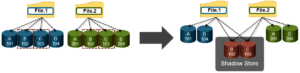
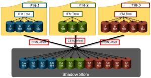
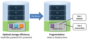
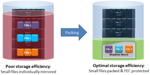
On discovering duplicate blocks, SmartDedupe moves a single copy of those blocks to a special set of files known as shadow stores. During this process, duplicate blocks are removed from the actual files and replaced with pointers to the shadow stores.

With post-process deduplication, new data is first stored on the storage device and then a subsequent process analyzes the data looking for commonality. This means that initial file write or modify performance is not impacted, since no additional computation is required in the write path.

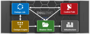
Under the covers, SmartDedupe is comprised of five principle components:

  • Deduplication Control Path
  • Deduplication Job
  • Deduplication Engine
  • Shadow Store
  • Deduplication Infrastructure

The SmartDedupe job  is a highly distributed background process that orchestrates deduplication across all the nodes in the cluster. Job control encompasses file system scanning, detection and sharing of matching data blocks, in concert with the Deduplication Engine.

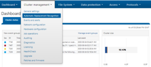
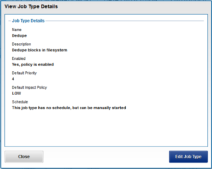
The SmartDedupe control path is the user interface portion, comprising the OneFS WebUI, command line interface and platform API, and is responsible for managing the configuration, scheduling and control of the deduplication job.

SmartDedupe works on data sets which are configured at the directory level, targeting all files and directories under each specified root directory. Multiple directory paths can be specified as part of the overall deduplication job configuration and scheduling. By design, the deduplication job will automatically ignore (not deduplicate) the reserved cluster configuration information located under the /ifs/.ifsvar/ directory, and also any file system snapshots.

It’s worth noting that the RBAC permissions required to configure and modify the deduplication settings are separate from those needed to actually run a deduplication job. For example, a user’s role must have job engine privileges to run a deduplication job. However, in order to configure and modify dedupe configuration settings, they must have the deduplication role privileges.

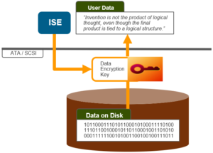
‘Fingerprinting’ is the part of the dedupe process where unique digital signatures, or fingerprints, are calculated using the SHA-1 hashing algorithm, one for each 8KB data block in the sampled set.

When SmartDedupe runs for the first time, it scans the data set and selectively samples blocks from it, creating the fingerprint index. This index contains a sorted list of the digital fingerprints, or hashes, and their associated blocks. After the index is created, the fingerprints are checked for duplicates. When a match is found, during the sharing phase, a byte-by-byte comparison of the blocks is performed to verify that they are absolutely identical and to ensure there are no hash collisions. Then, if they are determined to be identical, the block’s pointer is updated to the already existing data block and the new, duplicate data block is released.

Hash computation and comparison is only utilized during the sampling phase. For the actual block sharing phase, full data comparison is employed. SmartDedupe also operates on the premise of variable length deduplication, where the block matching window is increased to encompass larger runs of contiguous matching blocks.

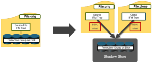
As we saw in the previous  article, OneFS shadow stores are file system containers that allow data to be stored in a sharable manner. This allows files to contain both physical data and pointers, or references, to shared blocks in shadow stores.

For example, consider the shadow store information for a regular, undeduped file:

# isi get -DDD file.orig | grep –i shadow

*  Shadow refs:        0

         zero=36 shadow=0 ditto=0 prealloc=0 block=28

A second copy of this file is then created and then deduped:

# isi get -DDD file.* | grep -i shadow

*  Shadow refs:        28

         zero=36 shadow=28 ditto=0 prealloc=0 block=0

*  Shadow refs:        28

         zero=36 shadow=28 ditto=0 prealloc=0 block=0

As we can see, the block count of the original file has now become zero and the shadow block count for both the original file and it’s and copy has become ‘28′. Additionally, if another file copy is added and deduplicated, the same shadow store info and count is reported for all three files.

It’s worth noting that, even if duplicate file(s) are removed, the original file still retains the shadow store layout.

Dedupe is performed in parallel across the cluster by the OneFS Job Engine via a dedicated deduplication job, which distributes worker threads across all nodes. This distributed work allocation model allows SmartDedupe to scale linearly as an Isilon cluster grows and additional nodes are added.

The control, impact management, monitoring and reporting of the deduplication job is performed by the Job Engine in a similar manner to other storage management and maintenance jobs on the cluster.

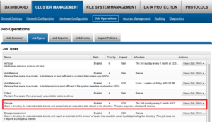
While deduplication can run concurrently with other cluster jobs, only a single instance of the deduplication job, albeit with multiple workers, can run at any one time. Although the overall performance impact on a cluster is relatively small, the deduplication job does consume CPU and memory resources.

Architecturally, the duplication job, and supporting dedupe infrastructure, are made up of the following four phases:

Because the SmartDedupe job is typically long running, each of the phases are executed for a set time period, performing as much work as possible before yielding to the next phase. When all four phases have been run, the job returns to the first phase and continues from where it left off. Incremental dedupe job progress tracking is available via the OneFS Job Engine reporting infrastructure.

Phase 1 – Sampling

In the sampling phase, SmartDedupe performs a tree-walk of the configured data set in order to collect deduplication candidates for each file. The rational is that a large percentage of shared blocks can be detected with only a smaller sample of data blocks represented in the index table.

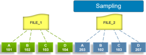
By default, the sampling phase selects one block from every sixteen blocks of a file as a deduplication candidate. For each candidate, a key/value pair consisting of the block’s fingerprint (SHA-1 hash) and file system location (logical inode number and byte offset) is inserted into the index. Once a file has been sampled, the file is flagged and won’t be re-scanned until it has been modified. This drastically improves the performance of subsequent deduplication jobs.

Phase 2 – Duplicate Detection

During the duplicate detection phase, the dedupe job scans the index table for fingerprints (or hashes) that match those of the candidate blocks.

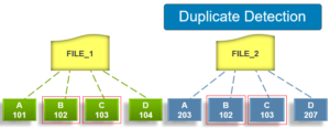
If the index entries of two files match, a request entry is generated.  In order to improve deduplication efficiency, a request entry also contains pre and post limit information. This information contains the number of blocks in front of and behind the matching block which the block sharing phase should search for a larger matching data chunk, and typically aligns to a OneFS protection group’s boundaries.

Phase 3 – Block Sharing

For the block sharing phase the deduplication job calls into the shadow store library and dedupe infrastructure to perform the sharing of the blocks.

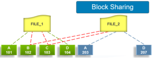
Multiple request entries are consolidated into a single sharing request, which is processed by the block sharing phase, and ultimately results in the deduplication of the common blocks. The file system searches for contiguous matching regions before and after the matching blocks in the sharing request; if any such regions are found, they will also be shared. Blocks are shared by writing the matching data to a common shadow store and creating references from the original files to this shadow store.

Phase 4 – Index Update

The index table is populated with the sampled and matching block information gathered during the previous three phases. After a file has been scanned by the dedupe job, OneFS may not find any matching blocks in other files on the cluster. Once a number of other files have been scanned, if a file continues to not share any blocks with other files on the cluster, OneFS will remove the index entries for that file. This helps prevent OneFS from wasting cluster resources searching for unlikely matches. SmartDedupe scans each file in the specified data set once, after which the file is marked, preventing subsequent dedupe jobs from rescanning the file until it has been modified.

HDFS Service not enabled by default in 9.0 OneFS – java.net.ConnectException: Connection refused

In OneFS 9.0 by default Services are not enabled by default, this also includes NFS, SMB, S3 and HDFS.

When attempting to use HDFS against an 9.0 cluster, the Hadoop client may see the following error on all HDFS access.

[cdh6-1-user1@centos-10 ~]$ hadoop fs -ls /

ls: Call From centos-10.foo.com/10.246.156.21 to cdh6.foo.com:8020 failed on connection exception: java.net.ConnectException: Connection refused; For more details see:  http://wiki.apache.org/hadoop/ConnectionRefused


This is because the HDFS service is not enabled on HDFS and therefore connections are refused.

When looking at the cluster we see the Service is Disabled as by design.

# isi services -al | grep hdfs

Available Services:

  hdfs                 HDFS Server                              Disabled


But when looking at the WebUI or the CLI, this misleading as the Service appears enabled

cascade-1# isi hdfs settings view

                 Service: Yes

      Default Block Size: 128M

   Default Checksum Type: none

     Authentication Mode: simple_only

          Root Directory: /ifs/data

         WebHDFS Enabled: Yes

           Ambari Server:

         Ambari Namenode:

             ODP Version:

    Data Transfer Cipher: none

Ambari Metrics Collector:

To enable the Service and allow HDFS connectivity, enable the hdfs service directly from the CLI.

isi services hdfs enable

# isi services -al | grep hdfs

Available Services:

  hdfs                 HDFS Server                              Enabled


Now the service is Enabled, HDFS operation can occur.

[cdh6-1-user1@centos-10 ~]$ hadoop fs -ls /

Found 11 items

-rwxrwxrwx   3 root         wheel               1 2020-02-20 11:38 /1.txt

-rwxrwxrwx   3 hbase        yarn               17 2020-02-20 11:31 /THIS_IS_ISILON_zone1-hadoop.txt

drwxr-xr-x   - hbase        hbase               0 2020-05-26 14:19 /_hbase

-rw-r--r--   3 root         wheel               0 2020-09-14 17:46 /cdh6_zone.txt

drwxr-xr-x   - hbase        hbase               0 2020-08-11 11:47 /hbase

-rw-r--r--   3 root         wheel               0 2020-09-14 17:46 /isilon_9.txt

drwxrwxrwx   - cdh6-1-user1 supergroup          0 2020-03-10 15:20 /nfs

drwxrwxr-x   - solr         solr                0 2019-12-12 13:29 /solr

drwxrwxrwt   - hdfs         supergroup          0 2019-12-12 13:29 /tmp

drwxr-xr-x   - hdfs         supergroup          0 2020-01-15 12:32 /user

-rw-r--r--   3 root         wheel               0 2020-09-14 17:47 /zone-3.txt


As an FYI: NFS, SMB & S3 are also Disabled by default in 9.0, but the Service checkbox/status can be managed via the WebUI Service enabled box on these services.

# isi services -al | grep smb

   smb                  SMB Service                              Disabled

Enable the Service via the WebUI:

# isi services -al | grep smb

   smb                  SMB Service                              Enabled

OneFS Shadow Stores – Part 2

In the previous article, we looked at an overview of the shadow store and its three primary use cases within OneFS. Now, let’s look at shadow store mechanics, reporting, and job engine integration.

Under the hood, OneFS provides a SIN cache, which helps facilitate shadow store allocations. This provides a mechanism to create a shadow store on demand when required, and then cache that shadow store in memory on the local node so that it can be shared with subsequent allocators. The SIN cache separates stores by disk pool, protection policy and whether or not the store is a container.

When referencing data in a shadow store, blocks are identified with a SIN (shadow identification number) and LBN pair. A file with shadow store blocks will have protection group (PG) information that points to SINs. For example:

# isi get -DD /ifs/data/file.dup | head -100

POLICY  W  LEVEL PERFORMANCE COAL  ENCODING      FILE              IADDRS

default  4+2/2 concurrency on    UTF-8         file.dup     <1,6,35008000:512>, <2,3,236753920:512>, <3,5,302813184:512> 

...

PROTECTION GROUPS

       lbn 0: 4+2/2

               4000:0001:0067:0009@0#64

               0,0,0:8192#32

The ‘isi get’ CLI command will display information about a particular shadow store when using the –L flag and the SIN:

# isi get –DDL <SIN>
# isi get -DDL 4000:0001:003c:0005 | head -20

isi: Could not find a path to LIN:0x40000001003c0005/SNAP:18446744073709551615: Invalid argument

No valid path for LIN 0x40000001003c0005

POLICY  W  LEVEL PERFORMANCE COAL  ENCODING      FILE              IADDRS

+2:1  18   4+2/2 concurrency off   N/A           <unlinked>        <1,9,168098816:512>, <2,6,269270016:512>, <3,6,33850368:512> ct:  1337648672 rt: 0

*************************************************

* IFS inode: [ 1,9,168098816:512, 2,6,269270016:512, 3,6,33850368:512 ]

*************************************************

*

*  Inode Version:      6

*  Dir Version:        2

*  Inode Revision:     1

*  Inode Mirror Count: 3

*  Recovered Flag:     0

*  Recovered Groups:   0

*  Link Count:         2

*  Size:               133660672

*  Mode:               0100000

*  Flags:              0

*  Physical Blocks:    19251

*  LIN:                4000:0001:003c:0005

The protection group information for a SIN will also contain ‘reference count’ (refcount) information.

lbn 384: 4+2/2

               1,4,5054464:8192#16

               1,7,450527232:8192#16

               2,9,411435008:8192#16

               2,11,556056576:8192#16

               3,5,678928384:8192#16

               3,8,579436544:8192#16

               REF(    384): { 3, 3, 3, 3, 3, 3, 3, 3 }

               REF(    392): { 3, 3, 3, 3, 3, 3, 3, 3 }

               REF(    400): { 3, 3, 3, 3, 3, 3, 3, 3 }

               REF(    408): { 3, 3, 3, 3, 3, 3, 3, 3 }

               REF(    416): { 3, 3, 3, 3, 3, 3, 3, 3 }

               REF(    424): { 3, 3, 3, 3, 3, 3, 3, 3 }

               REF(    432): { 3, 3, 3, 3, 3, 3, 3, 3 }

               REF(    440): { 3, 3, 3, 3, 3, 3, 3, 3 }

The isi_sstore stats command can be used to display aggregate container statistics, alongside those of regular, or block, shadow stores. The output also includes storage efficiency stats. For example:

# isi_sstore stats

Block SIN stats:

33 GB user data takes 6 MB in shadow stores, using 11 MB physical space.

10792K physical average per shadow store.


5708.92 refs per block.

Reference efficiency 99.9825%.

Storage efficiency 57.0892%


Container SIN stats:

0 B user data takes 0 B in shadow stores, using 0 B physical space.


Raw counts={ type 0 num_ss=1 lsize=6209536 pblk=1349 refs=4328123 }{ type 1 num_ss=0 lsize=0 pblk=0 refs=0 }

Running the ‘isi_sstore list’ command in its verbose (-v) form also displays the type of SIN, the ‘fragmentation score’ (frag score) metric and whether a container is ‘underfull’, amongst other things:

# isi_sstore list –v | head –n 2

SIN                 lsize   psize    refs    filesize date         sin type underfull frag score

4000:0001:0002:0000 6209536 11003392 4328123 2121080K Jan 29 21:09 block    no 0.01

When it comes to the job engine, there are several jobs that interact with and cater to shadow stores – in addition to the dedupe job and SmartPools for small file packing. These include:

The Flexprotect job has two phases which are of particular relevance to shadow stores.

  1. The ‘LIN reverify’ phase: Metatree transfers are allowed, even if a file is under repair. Since metatree transfer goes in opposite direction from linscan, the LIN table needs to be re-verified to ensure a file is not missed during the first LIN verify. Note that both LIN verify and reverify will scan only the LIN potion of the LIN table.
  2. The ‘SIN verify’ phase: Once it’s determined that all the LINs are good, the SINs are inspected to ensure they are all correct. This is necessary since a cloning operation during Flexprotect, for example, might have moved an un-repaired block to a shadow store. This phase scans only the SIN portion of the table.

In general, the collect job isn’t required for (logical) blocks stored in shadow stores isn’t, since the freeing system is resilient to failure. The one exception is that references from files intentionally leaked by removing a LIN table entry to a file will not be freed, so collect will deal with these.

The ShadowStoreDelete job examines each shadow store for allocated blocks that have no external references (other than the shadow store’s reference) and frees the blocks. If all blocks in a shadow store have been freed then the shadow store is removed. A good practice is to run the ShadowStoreDelete job prior to running IntegrityScan on clusters with file clones and/or running SmartDedupe or small file storage efficiency jobs.

The ShadowStoreProtect job updates the protection level of shadow stores which are referenced by a LIN with a higher requested protection. Shadow stores that require a protection level change are added to a persistent queue (PQ) and consumed by this job.

There is also a SinReport job engine job which can be run to find LINs with SINs within the file system.

All the jobs which can change the protection contain an additional phase for SINs. For every LIN pointing to a particular SIN, if the LINs new protection policy is higher than that of the shadow store, it will update the SIN’s protection policy. In the SIN phase, the highest recorded policy will be used to protect the shadow store. In the case of disk pools, shadow stores may inherit the effective protection from the disk pool but not the disk pool itself.

As we have seen, to a large degree shadow stores store data like regular files. However, blocks from regular files are moved or copied to shadow stores and the original blocks in the source file are replaced with references to the blocks in the shadow store. If any of the logical blocks in the source file are written to, a copy on write (COW) event is triggered, which causes a local allocation of a block for the source file to replace the shadow reference. There may be multiple files with references to the same logical block in a shadow store. When all external references to a block in a shadow store have been released the block in the shadow store is now unused and will never be referenced again. The background garbage collection job, ShadowStoreDelete, periodically scans all the shadow stores and frees these unreferenced blocks. Once all the blocks in a shadow store are released, the shadow store itself can then be removed.

Be aware that files which reference shadow stores may also behave differently from regular files in that reading shadow-store references can be slower than reading data directly. Specifically, reading non-cached shadow-store references is slower than reading non-cached data. Reading cached shadow-store references takes no more time than reading cached data.

When files that reference shadow stores are replicated to another Isilon cluster or backed up via NDMP, the shadow stores are not transferred to the target Isilon cluster or backup device. The files are transferred as if they contained the data that they reference from shadow stores. On the target Isilon cluster or backup device, the files consume the same amount of space as if they had not referenced shadow stores.

When OneFS creates a shadow store, OneFS assigns the shadow store to a storage pool of a file that references the shadow store. If you delete the storage pool that a shadow store resides on, the shadow store is moved to a pool occupied by another file that references the shadow store.

OneFS does not delete a shadow-store block immediately after the last reference to the block is deleted. Instead, OneFS waits until the ShadowStoreDelete job is run to delete the unreferenced block. If a large number of unreferenced blocks exist on the cluster, OneFS might report a negative deduplication savings until the ShadowStoreDelete job is run.

Shadow stores are protected at least as much as the most protected file that references it. For example, if one file that references a shadow store resides in a storage pool with +2 protection and another file that references the shadow store resides in a storage pool with +3 protection, the shadow store is protected at +3.

Quotas account for files that reference shadow stores as if the files contained the data referenced from shadow stores; from the perspective of a quota, shadow-store references do not exist. However, if a quota includes data protection overhead, the quota does not account for the data protection overhead of shadow stores.

OneFS Shadow Stores

Within OneFS, the shadow store is a class of system file that contains blocks which can be referenced by different file – thereby providing a mechanism that allows multiple files to share common data. Shadow stores were first introduced in OneFS 7.0, initially supporting Isilon file clones, and indeed there are many overlaps between cloning and deduplicating files. As we will see, a variant of shadow store is also used as a container for file packing in OneFS SFSE (Small File Storage Efficiency), often used in archive workflows such as healthcare’s PACS.

Architecturally, each shadow store can contain up to 256 blocks, with each block able to be referenced by 32,000 files. If this 32KB reference limit is exceeded, a new shadow store is created. Additionally, shadow stores do not reference other shadow stores. All blocks within a shadow store must be either sparse or point at an actual data block. And snapshots of shadow stores are not allowed, since shadow stores have no hard links.

Shadow stores contain the physical addresses and protection for data blocks, just like normal file data. However, a fundamental difference between a shadow stores and a regular file is that the former doesn’t contain all the metadata typically associated with traditional file inodes. In particular, time-based attributes (creation time, modification time, etc) are explicitly not maintained.

Consider the shadow store information for a regular, undeduped file (file.orig):

# isi get -DDD file.orig | grep –i shadow

*  Shadow refs:        0

         zero=36 shadow=0 ditto=0 prealloc=0 block=28

A second copy of this file (file.dup) is then created and then deduplicated:

# isi get -DDD file.* | grep -i shadow

*  Shadow refs:        28

         zero=36 shadow=28 ditto=0 prealloc=0 block=0

*  Shadow refs:        28

         zero=36 shadow=28 ditto=0 prealloc=0 block=0

As we can see, the block count of the original file has now become zero and the shadow count for both the original file and its copy is incremented to ‘28′. Additionally, if another file copy is added and deduplicated, the same shadow store info and count is reported for all three files. It’s worth noting that even if the duplicate file(s) are removed, the original file will still retain the shadow store layout.

Each shadow store has a unique identifier called a shadow inode number (SIN). But, before we get into more detail, here’s a table of useful terms and their descriptions:

Element Description
Inode Data structure that keeps track of all data and metadata (attributes, metatree blocks, etc.) for files and directories in OneFS
LIN Logical Inode Number uniquely identifies each regular file in the filesystem.
LBN Logical Block Number  identifies the block offset for each block in a file
IFM Tree or Metatree Encapsulates the on-disk and in-memory format of the inode. File data blocks are indexed by LBN in the IFM B-tree, or file metatree. This B-tree stores protection group (PG) records keyed by the first LBN. To retrieve the record for a particular LBN, the first key before the requested LBN is read. The retried record may or may not contain actual data block pointers.
IDI Isi Data Integrity checksum. IDI checkcodes help avoid data integrity issues which can occur when hardware provides the wrong data, for example. Hence IDI is focused on the path to and from the drive and checkcodes are implemented per OneFS block.
Protection Group (PG) A protection group encompasses the data and redundancy associated with a particular region of file data. The file data space is broken up into sections of 16 x 8KB blocks called stripe units. These correspond to the N in N+M notation; there are N+M stripe units in a protection group.
Protection Group Record Record containing block addresses for a data stripe .There are five types of PG records: sparse, ditto, classic, shadow, and mixed. The IFM B-tree uses the B-tree flag bits, the record size, and an inline field to identify the five types of records.
BSIN Base Shadow Store, containing cloned or deduped data
CSIN Container Shadow Store, containing packed data (container or files).
SIN Shadow Inode Number is a LIN for a Shadow Store, containing blocks that are referenced by different files; refers to a Shadow Store
Shadow Extent Shadow extents contain a Shadow Inode Number (SIN), an offset, and a count.

Shadow extents are not included in the FEC calculation since protection is provided by the shadow store.

Blocks in a shadow store are identified with a SIN and LBN (logical block number).

# isi get -DD /ifs/data/file.dup | fgrep –A 4 –i “protection group”

PROTECTION GROUPS

       lbn 0: 4+2/2

               4000:0001:0067:0009@0#64

               0,0,0:8192#32

A SIN is essentially a LIN that is dedicated to a shadow store file, and SINs are allocated from a subset of the LIN range. Just as every standard file is uniquely identified by a LIN, every shadow store is uniquely identified by a SIN. It is easy to tell if you are dealing with a shadow store because the SIN will begin with 4000. For example, in the output above:

4000:0001:0067:0009

Correspondingly, in the protection group (PG) they are represented as:

  • SIN
  • Block size
  • LBN
  • Run

The referencing protection group will not contain valid IDI data (this is with the file itself). FEC parity, if required, will be computed assuming a zero block.

When a file references data in a shadow store, it contains meta-tree records that point to the shadow store. This meta-tree record contains a shadow reference, which comprises a SIN and LBN pair that uniquely identifies a block in a shadow store.

A set of extension blocks within the shadow store holds the reference count for each shadow store data block. The reference count for a block is adjusted each time a reference is created or deleted from any other file to that block. If a shadow store block’s reference count drop to zero, it is marked as deleted, and the ShadowStoreDelete job, which runs periodically, deallocates the block.

Be aware that shadow stores are not directly exposed in the filesystem namespace. However, shadow stores and relevant statistics can be viewed using the ‘isi dedupe stats’, ‘isi_sstore list’ and ‘isi_sstore stats’ command line utilities.

Cloning

In OneFS, files can easily be cloned using the ‘cp –c’ command line utility. Shadow store(s) are created during the file cloning process, where the ownership of the data blocks is transferred from the source to the shadow store.

In some instances, data may be copied directly from the source to the newly created shadow stores. Cloning uses logical references to shadow stores, and the source and the destination data blocks refer to an offset in a shadow store. The source file’s protection group(s) are moved to a shadow store, and the PG is now referenced by both the source file and destination clone file. After cloning a file, both the source and the destination data blocks refer to an offset in a shadow store.

Dedupe

Shadow Stores are also used for both OneFS in-line deduplication and post-process SmartDedupe. The principle difference with dedupe, as compared to cloning, is the process by which duplicate blocks are detected.

Since in-line dedupe and SmartDedupe use different hashing algorithms, the indexes for each are not shared directly. However, the work performed by each dedupe solution can be leveraged by each other.  For instance, if SmartDedupe writes data to a shadow store, when those blocks are read, the read hashing component of inline dedupe will see those blocks and index them.

SmartDedupe post process dedupe is compatible with in-line data reduction and vice versa. In-line compression is able to compress OneFS shadow stores. However, for SmartDedupe to process compressed data, the SmartDedupe job will have to decompress it first in order to perform deduplication, which is an addition resource overhead.

Currently neither SmartDedupe nor in-line dedupe are immediately aware of the duplicate matches that each other finds.  Both in-line dedupe and SmartDedupe could dedupe blocks containing the same data to different shadow store locations, but OneFS is unable to consolidate the shadow blocks together.  When blocks are read from a shadow store into L1 cache, they are hashed and added into the in-memory index where they can be used by in-line dedupe.

Unlike SmartDedupe, in-line dedupe can deduplicate a run of consecutive blocks to a single block in a shadow store. In contrast, the SmartDedupe job also has to spend more effort to ensure that contiguous file blocks are generally stored in adjacent blocks in the shadow store. If not, both read and degraded read performance may be impacted.

Small File Storage Efficiency

A class of specialized shadow stores are also used as containers for storage efficiency, allowing packing of small file into larger structures that can be FEC protected.

These shadow stores differ from regular shadow stores in that they are deployed as single-reference stores. Additionally, container shadow stores are also optimized to isolate fragmentation, support tiering, and live in a separate subset of ID space from regular shadow stores. (4080:xxxx:xxxx:xxxx).

OneFS Instant Secure Erase

There are a several notable problems with many common drive retirement practices. Although not all of them are related to information security, many still result in excess cost. For example, companies that decide to re-purpose their hardware may choose to overwrite the data rather than erase it completely. The process itself is both time consuming, and a potential data security risk. For example, since re-allocated sectors on the drives are not covered by the overwrite process, this means that some old information will remain on disk.

Another option is to degauss and physically shred drives when the storage hardware is retired. Degaussing can yield mixed results, since different drives require unique optimal degauss strengths. This also often leads to readable data being left on the drive.

Thirdly, there is the option to hire professional disposal services to destroy the drive. However, the more people handling the data, the higher the data vulnerability. Total costs can also increase dramatically because of the need to publish internal reports and any auditing fees.

To address these issues, OneFS includes Instant Secure Erase (ISE) functionality. ISE enables the cryptographic erasure of non-SEDs drives in an Isilon cluster, providing customers with the ability to erase the contents of a drive after smartfail.

But first, some key terminology:

Term Definition
Cryptographic Erase ‘SANITIZE’ command sets for SCSI/ATA drive is defined by the T10/T13 technical committees, respectively.
Instant Secure Erase The industry term referring to the drive’s ‘cryptographic erase’ capability.
isi_drive_d The OneFS drive daemon that manages the various drive states/activities, mapping devices to physical drive slots, and supporting firmware updates.


So OneFS ISE uses the ‘cryptographic erase’ command to erase proprietary user data on supported drives. ISE is enabled by default and automatically performed upon OneFS Smart-failing a supported drive.

ISE can also be run manually against a specific drive. To do this, it sends standard commands to the drive, depending on its interface type. For example:

  • SCSI: “SANITIZE (cryptographic)”
  • ATA: “CRYPTO SCRAMBLE EXT”

If the drive firmware supports the appropriate above command, it swaps out the Data Encryption key to render data on the storage media unreadable.

In order to use ISE, the following requirements must be met:

  • The cluster is running OneFS 8.2.1 or later.
  • The node is not a SED-configuration (for automatic ISE action upon smartfail).
  • User has privileges to run related CLI commands (for manually performed ISE).
    • For example, the privilege to run ‘isi_radish’.
  • Cluster contains currently supported drives:
    • SCSI / ATA interface.
    • Supports “cryptographic erase” command.
  • The target drive is present.

ISE can be invoked by the following methods:

  1. Via the isi_drive_d daemon during a drive Smartfail.
    • If the node is non-SED configuration.
    • Configurable through ‘drive config’.
  2. Manually, by running the ‘isi_radish’ command.
  3. Programmatically, by executing the python ‘isi.hw.bay’ module.

As mentioned previously, ISE is enabled by default. If this is not desired, it can be easily disabled from the OneFS CLI with the following syntax:

# isi devices drive config modify --instant-secure-erase no

The following CLI command can also be used to manually run ISE:

# isi_radish -S <bay/dev>

ISE provides fairly comprehensive logging, and the results differ slightly depending on whether it is run manually or automatically during a smartfail. Additionally, the ‘isi device drive list’ CLI command output will display the drive state. For example:

State Context
SMARTFAIL During ISE action
REPLACE After ISE finish

Note that an ISE failure or error will not block the normal smartfail process.

For a manual ISE run against a specific drive, the results are both displayed on the OneFS CLI console and written to /var/log/messages.

The ISE logfile warning messages include:

Action Log Entry
Running ISE “Attempting to erase smartfailed drive in bay N …”,

“Drive in bay N is securely erased”

(isi_drive_history.log) “is securely erased: bay:N unit:N dev:daN Lnum:N seq:N model:X …”

ISE not supported “Drive in bay N is not securely erased, because it doesn’t support crypto sanitize.”
ISE disabled in drive config “Smartfailed drive in bay N is not securely erased. instant-secure-erase disabled in drive_d config.”
ISE error “Drive in bay N is not securely erased, attempt failed.”

“Drive in bay N is not securely erased, can’t determine if it supports crypto sanitize.”

(isi_drive_history.log) “failed to be securely erased: bay:N unit:N dev:daN Lnum:N seq:N model:X …”

When troubleshooting ISE, a good first move is using the CLI ‘grep’ utility to search for the keyword ‘erase’ in log files.

Symptom Detail
ISE was successful but took too long to run •       It depends on drive model, but usually < 1minute

•       It may block other process from accessing the drive.


ISE reports error •       Usually it’s due to CAM got error sending sanitize commands

•       Looking at console & /var/log/messages & dmesg for errors during ISE activity timeframe

–         Did CAM report error?

–         Did the device driver / expander report error?

–         Did the drive/device drop during sanitize activity?


OneFS Performance Dataset Monitoring

As clusters increase in scale and the number of competing workloads place demands on system resources, more visibility is required in order to share cluster resources equitably. OneFS partitioned performance monitoring helps define, monitor and react to performance-related issues on the cluster. This allows storage admins to pinpoint resource consumers, helping to identify rogue workloads, noisy neighbor processes, or users that consume excessive system resources.

Partitioned performance monitoring can be used to define workloads and view the associated performance statistics – protocols, disk ops, read/write bandwidth, CPU, IOPs, etc. Workload definitions can be quickly and simply configured to include any combination of directories, exports, shares, paths, users, clients and access zones. Customized settings and filters can be crafted to match specific workloads for a dataset that meets the required criteria, and reported statistics are refreshed every 30 seconds. Workload monitoring is also key for show-back and charge-back resource accounting.

Category Description Example
Workload A set of identification metrics and resource consumption metrics. {username:nick, zone_name:System} consumed {cpu:1.2s, bytes_in:10K, bytes_out:20M, …}
Dataset A specification of identification metrics to aggregate workloads by, and the workloads collected that match that specification. {username, zone_name}
Filter A method for including only workloads that match specific identification metrics. {zone_name:System}

Each resource listed below is tracked by certain stages of partitioned performance monitoring to provide statistics within a performance dataset, and for limiting specific workloads.

Resource Name Definition First Introduced
CPU Time Measures CPU utilization. There are two different measures of this at the moment; raw measurements are taken in CPU cycles, but they are normalized to microseconds before aggregation. OneFS 8.0.1
Reads A count of blocks read from disk (including SSD). It generally counts 8 KB file blocks, though 512-byte inodes also count as a full block. These are physical blocks, not logical blocks, which doesn’t matter much for reads, but is important when analyzing writes. OneFS 8.0.1
Writes A count of blocks written to disk; or more precisely, to the journal. As with reads, 512-byte inode writes are counted as full blocks; for files, 8 KB blocks. Since these are physical blocks, writing to a protected file will count both the logical file data and the protection data. OneFS 8.0.1
L2 Hits A count of blocks found in a node’s L2 (Backend RAM) cache on a read attempt, avoiding a read from disk. OneFS 8.0.1
L3 Hits A count of blocks found in a node’s L3 (Backend SSD) cache on a read attempt, replacing a read from disk with a read from SSD. OneFS 8.0.1
Protocol Operations ·         Protocol (smb1,smb2,nfs3, nfs4, s3)

·         NFS in OneFS 8.2.2 and later

·         SMB in OneFS 8.2 and later

·         S3 in OneFS 9.0

·         For SMB 1, this is the number of ops (commands) on the wire with the exception of the NEGOTIATE op.

·         For SMB 2/3 this is the number of chained ops (commands) on the wire, with the exception of the NEGOTIATE op.

·         The counted op for chained ops will always be the first op.

·         SMB NEGOTIATE ops will not be associated with a specific user.

OneFS 8.2.2
Bytes In A count of the amount of data received by the server from a client, including the application layer headers but not including TCP/IP headers. OneFS 8.2
Bytes Out A count of the amount of data sent by the server to a client, including the application layer headers but not including TCP/IP headers. OneFS 8.2
Read/Write/Other Latency Total Sum of times taken from start to finish of ops as they run through the system identical to that provided by isi statistics protocol. Specifically, this is the time in between LwSchedWorkCreate and the final LwSchedWorkExecuteStop for the work item. Latencies are split between the three operations types, read/write/other, with a separate resource for each.

Use Read/Write/Other Latency Count to calculate averages

OneFS 8.2
Read/Write/Other Latency Count Count of times taken from start to finish of ops as they run through the system identical to that provided by isi statistics protocol. Latencies are split between the three operations types, read/write/other, with a separate resource for each.

Used to calculate the average of Read/Write/Other Latency Total

OneFS 8.2
Workload Type ·         Dynamic (or blank) – Top-N tracked workload

·         Pinned – Pinned workload

·         Overaccounted – The sum of all stats that have been counted twice within the same dataset, used so that a workload usage % can be calculated.

·         Excluded – The sum of all stats that do not match the current dataset configuration. This is for workloads that do not have an element specified that is defined in the category, or for workloads in filtered datasets that do not match the filter conditions.

·         Additional – The amount of resources consumed by identifiable workloads not matching any of the above. Principally any workload that has dropped off of the top-n.

·         System – The amount of resources consumed by the kernel.

·         Unknown – The amount of resources that we could not attribute to any workload, principally due to falling off of kernel hashes of limited size.

OneFS 8.2

Identification Metrics are the client attributes of a workload interacting with OneFS through Protocol Operations, or System Jobs or Services. They are used to separate each workload into administrator-defined datasets.

Metric Name Definition First Introduced
System Name The system name of a given workload. For services started by isi_mcp/lwsm/isi_daemon this is the service name itself. For protocols this is inherited from the service name. For jobs this is the job id in the form “Job: 123”. OneFS 8.0.1
Job Type + Phase A short containing the job type as the first n bytes, and the phase as the rest of the bytes. There are translations for job type to name, but not job phase to name. OneFS 8.0.1
Username The user as reported by the native token. Translated back to username if possible by IIQ / stat summary view. OneFS 8.2
Local IP IP Address, CIDR Subnet or IP Address range of the node serving that workload. CIDR subnet or range will only be output if a pinned workload is configured with that range. There is no overlap between addresses/subnets/ranges for workloads with all other metrics matching. OneFS 8.2
Remote IP IP Address, CIDR Subnet or IP Address range of the client causing this workload. CIDR subnet or range will only be output if a pinned workload is configured with that range. There is no overlap between addresses/subnets/ranges for workloads with all other metrics matching. OneFS 8.2
Protocol Protocol enumeration index. Translated to string by stat.

·         smb1, smb2

·         nfs3, nfs4

·         s3

OneFS 8.2, OneFS 8.2.2, & OneFS 9.0
Zone The zone id of the current workload. If zone id is present all username lookups etc should use that zone, otherwise it should use the default “System” zone. Translation to string performed by InsightIQ / summary view. OneFS 8.0.1
Group The group that the current workload belongs to. Translated to string name by InsightIQ / summary view. For any dataset with group defined as an element the primary group will be tracked as a dynamic workload (unless there is a matching pinned workload in which case that will be used instead). If there is a pinned workload/filter with a group specified, the additional groups will also be scanned and tracked. If multiple groups match then stats will be double accounted, and any double accounting will be summed in the “Overaccounted” workload within the category. OneFS 8.2
IFS Domain The partitioned performance IFS domain and respective path LIN that a particular file belongs to, determined using the inode. Domains are not tracked using dynamic workloads unless a filter is created with the specified domain. Domains are created/deleted automatically by configuring a pinned workload or specifying a domain in a filter. A file can belong to multiple domains in which case there will be double accounting within the category. As with groups any double accounting will be summed in the “Overaccounted” workload within the category. The path must be resolved from the LIN by InsightIQ or the Summary View. OneFS 8.2
SMB Share Name The name of the SMB share that the workload is accessing through, provided by the smb protocol. Also provided at the time of actor loading are the Session ID and Tree ID to improve hashing/dtoken lookup performance within the kernel. OneFS 8.2
NFS Export ID The ID of the NFS export that the workload is accessing through, provided by the smb protocol. OneFS 8.2.2
Path Track and report SMB traffic on a specified /ifs directory path. Note that NFS traffic under a monitored path is excluded OneFS 8.2.2

So how does this work in practice? From the CLI, the following command syntax can be used to create a standard performance dataset monitor:

# isi performance dataset create –-name <name> <metrics>

For example:

# isi performance dataset create --name my_dataset username zone_name

To create a dataset that requires filters, use:

# isi performance dataset create –-name <name> <metrics> –-filters <filter-metrics>

# isi performance dataset create --name my_filtered_dataset username zone_name --filters zone_name

For example, to monitor the NFS exports in access zones:

# isi performance datasets create --name=dataset01 export_id zone_name

# isi statistics workload list --dataset=dataset01

Or to monitor by username for NFSv3 traffic only

# isi performance datasets create --name=ds02 username protocol --filters=protocol

# isi performance filters apply ds02 protocol:nfs3

# isi statistics workload list --dataset=ds02

Other performance dataset operation commands include:

# isi performance dataset list

# isi performance dataset view <name|id>

# isi performance dataset modify <name|id> --name <new_name>

# isi performance dataset delete <name|id>

A dataset will display the top 1024 workloads by default. Any remainder will be aggregated into a single additional workload.

If you want a workload to always be visible, it can be pinned using the following syntax:

# isi performance workload pin <dataset_name|id> <metric>:<value>

For example:

# isi performance workload pin my_dataset username:nick zone_name:System

Other workload operation commands include:

# isi performance workload list <dataset_name|id>

# isi performance workload view <dataset_name|id> <workload_name|id>

# isi performance workload modify <dataset_name|id> <workload_name|id> --name <new_name>

# isi performance workload unpin <dataset_name|id> <workload_name|id>

Multiple filters can also be applied to the same dataset. A workload will be included if it matches any of the filters. Any workload that doesn’t match a filter be aggregated into an excluded workload.

The following CLI command syntax can be sued to apply a filter:

# isi performance filter apply <dataset_name|id> <metric>:<value>

For example:

# isi performance filter apply my_filtered_dataset zone_name:System

Other filter options include:

# isi performance filter list <dataset_name|id>

# isi performance filter view <dataset_name|id> <filter_name|id>

# isi performance filter modify <dataset_name|id> <filter_name|id> --name <new_name>

# isi performance filter remove <dataset_name|id> <filter_name|id>

The following syntax can be used to enable path tracking. For example, to monitor traffic under /ifs/data:

# isi performance datasets create –name=dataset1 path

# isi performance workloads pin dataset1 path:/ifs/data/

Be aware that NFS traffic under a monitored path is currently not reported. For example:

The following CLI command can be used to define and view statistics for a dataset:

# isi statistics workload –-dataset <dataset_name|id>

For example:

# isi statistics workload --dataset my_dataset

    CPU  BytesIn  BytesOut   Ops  Reads  Writes   L2   L3  ReadLatency  WriteLatency  OtherLatency  UserName   ZoneName  WorkloadType

-------------------------------------------------------------------------------------------------------------------------------------

 11.0ms     2.8M     887.4   5.5    0.0   393.7  0.3  0.0      503.0us       638.8us         7.4ms       nick     System             -

  1.2ms    10.0K     20.0M  56.0   40.0     0.0  0.0  0.0        0.0us         0.0us         0.0us      mary     System        Pinned

 31.4us     15.1      11.7   0.1    0.0     0.0  0.0  0.0      349.3us         0.0us         0.0us       nick Quarantine             -

166.3ms      0.0       0.0   0.0    0.0     0.1  0.0  0.0        0.0us         0.0us         0.0us         -          -      Excluded

 31.6ms      0.0       0.0   0.0    0.0     0.0  0.0  0.0        0.0us         0.0us         0.0us         -          -        System

 70.2us      0.0       0.0   0.0    0.0     3.3  0.1  0.0        0.0us         0.0us         0.0us         -          -       Unknown

  0.0us      0.0       0.0   0.0    0.0     0.0  0.0  0.0        0.0us         0.0us         0.0us         -          -    Additional

  0.0us      0.0       0.0   0.0    0.0     0.0  0.0  0.0        0.0us         0.0us         0.0us         -          - Overaccounted

-------------------------------------------------------------------------------------------------------------------------------------

Total: 8

Includes standard statistics flags, i.e. --numeric, --sort, --totalby etc..

Other useful commands include the following:

To list all available identification metrics:

# isi performance metrics list

# isi performance metrics view <metric>

To view/modify the quantity of top workloads collected per dataset:

# isi performance settings view

# isi performance settings modify <n_top_workloads>

To assist with troubleshooting, the validation of the configuration is thorough, and errors are output directly to the CLI. Name lookup failures, for example UID to username mappings, are reported in an additional column in the statistics output. Errors in the kernel are output to /var/log/messages and protocol errors are written to the respective protocol log.

Note that statistics are updated every 30 seconds and, as such, a newly created dataset will not show up in the statistics output until the update has occurred. Similarly, an old dataset may be displayed until the next update occurs.

A dataset with a filtered metric specified but with no filters applied will not output any workloads. Paths and Non-Primary groups are only reported if they are pinned or have a filter applied. Paths and Non-Primary groups may result in work being accounted twice within the same dataset, as they can match multiple workloads. The total amount over-accounted within a dataset is aggregated into the Overaccounted workload.

As mentioned previously, the NFS, SMB, and S3 protocols are now supported in OneFS 9.0. Other primary protocol monitoring support, such as HDFS, will be added in a future release.

In addition to protocol stats, OneFS also includes job performance resource monitoring, which provides statistics for the resources used by jobs – both cluster-wide and per-node. Available in a ‘top’ format, this command displays the top jobs and processes, and periodically updates the information.

For example, the following syntax shows, and indefinitely refreshes, the top five processes on a cluster:

# isi statistics workload --limit 5 –-format=top

last update:  2020-07-11T06:45:25 (s)ort: default

CPU   Reads Writes      L2    L3    Node  SystemName        JobType

1.4s  9.1k  0.0         3.5k  497.0 2     Job:  237         IntegrityScan[0]

1.2s  85.7  714.7       4.9k  0.0   1     Job:  238         Dedupe[0]

1.2s  9.5k  0.0         3.5k  48.5  1     Job:  237         IntegrityScan[0]

1.2s  7.4k  541.3       4.9k  0.0   3     Job:  238         Dedupe[0]

1.1s  7.9k  0.0         3.5k  41.6  2     Job:  237         IntegrityScan[0]

The resource statistics tracked per job, per job phase, and per node include CPU, reads, writes, and L2 & L3 cache hits. Unlike the output from the ‘top’ command, this makes it easier to diagnose individual job resource issues, etc.

OneFS and 16TiB Large File Support

The largest file size that OneFS currently supports was raised to 16TB in the OneFS 8.2.2 release – a fourfold increase over the previous maximum of 4TB.

This helps enable additional applications and workloads that typically deal with large files, for example videos & images, seismic analysis workflows, as well as a destination or staging area for backups and large database dumps.

Firstly, large file support is available for free. No special license is required to activate large file support and, once enabled, files larger than 4TiB may be written to and/or exist on the system. However, large file support cannot be disabled once enabled.

In order for OneFS to support files larger than 4TB, adequate space is required in all of a cluster’s disk pools in order to avoid a potential performance impact. As such, the following requirements must be met in order to enable large file support:

Large File Support Requirement Description
Version A cluster must be running OneFS 8.2.2 in order to enable large file support.
Disk Pool A maximum sized file (16TB) plus protection can consume no more than 10% of any disk pool. This translates to a minimum disk pool size of 160TB plus protection.
SyncIQ Policy All SyncIQ remote clusters must be running OneFS 8.2.2 and also satisfy the restrictions for minimum disk pool size and SyncIQ policies.

Note that the above restrictions will be removed in a future release, allowing support for large (>4TiB) file sizes on all cluster configurations.

The following procedure can be used to configure a cluster for 16TiB file support:


Once a cluster is happily running OneFS 8.2.2 or later, the ‘isi_large_file -c’ CLI utility will verify that the cluster’s disk pools and existing SyncIQ policies meet the requirements listed above. For example:

# isi_large_file -c

Checking cluster compatibility with large file support...


NOTE:

Isilon requires ALL clusters in your data-center that are part of

any SyncIQ relationship to be running on versions of OneFS compatible

with large file support before any of them can enable it.  If any

cluster requires upgrade to a compatible version, all SyncIQ policies

in a SyncIQ relationship with the upgraded cluster will need to resync

before you can successfully enable large file support.


* Checking SyncIQ compatibility...

- SyncIQ compatibility check passed


* Checking cluster disk space compatibility...

- The following disk pools do not have enough usable storage capacity to support                   large files:


Disk Pool Name    Members     Usable  Required  Potential  Capable  Add Nodes

-----------------------------------------------------------------------------

h500_30tb_3.2tb-ssd_128gb:2  2-3,6,8,10-11,13-16,18-19:bay3,6,9,12,15   107TB                     180TB      89T      N        X

h500_30tb_3.2tb-ssd_128gb:3  2-3,6,8,10-11,13-16,18-19:bay4,7,10,13,16  107TB                     180TB      89T      N        X

h500_30tb_3.2tb-ssd_128gb:4  2-3,6,8,10-11,13-16,18-19:bay5,8,11,14,17  107TB                     180TB      89T      N        X

h500_30tb_3.2tb-ssd_128gb:9  1,4-5,7,9,12,17,20-24:bay5,7,11-12,17      107TB                     180TB      89T      N        X

h500_30tb_3.2tb-ssd_128gb:10 1,4-5,7,9,12,17,20-24:bay4,6,10,13,16      107TB                     180TB      89T      N        X

h500_30tb_3.2tb-ssd_128gb:11 1,4-5,7,9,12,17,20-24:bay3,8-9,14-15       107TB                     180TB      89T      N        X


The cluster is not compatible with large file support:

  - Incompatible disk pool(s)

Here, the output shows that none of the pools meet the 10% disk pool rule above and contain insufficient storage capacity to allow large file support to be enabled. In this case, additional nodes would need to be added.

The following table explains the detail of output categories above:

Category Description
Disk Pool Name Node pool name and this disk pool ID.
Members Current nodes and bays in this disk pool .
Usable Current usable capacity of this disk pool.
Required Usable capacity required for this disk pool to support large files.
Potential The max usable capacity this disk pool could support at the target node count
Capable Whether this disk pool has the size of disk and number per node to support large files
Add Nodes If this disk pool is capable, how many more nodes need to be added


Once the validation confirms that the cluster meets the requirements, the following CLI command can then be run to enable large file support:

# isi_large_file -e

Upon successfully enabling large file support, the ‘cluster full’ alert threshold is automatically lowered to 85% from the OneFS default of 95%. This is to ensure that adequate space is available for large file creation, repair, and restriping. Additionally, any SyncIQ replication partners must also be running OneFS 8.2.2 or later, adhere to the above minimum disk pool size, and have the large file feature enabled.

Any disk pool management commands that violate the large file support requirements are not allowed. Once enabled, disk pools are periodically checked for compliance and OneFS will alert if a disk pool fails to meet the minimum size requirement.

If Large File Support is enabled on a cluster, any SyncIQ replication policies will only succeed with remote clusters that are also running 8.2.2 or later and have Large File Support enabled. All other SyncIQ policies will fail until the appropriate remote clusters are upgraded and have large file support switched on.

Be aware that, once enabled, large file support cannot be disabled on a cluster – regardless of whether it’s a SyncIQ source or target, or not participating in replication. This may impact future expansion planning for the cluster and all of its SyncIQ replication partners.

Also note that, after enabling large file support, the ‘cluster full’ alert threshold is automatically lowered to 85% from the default of 95%. This helps ensure that adequate space is available for large file creation, repair, and restriping.

When the maximum filesize is exceeded, OneFS typically returns an ‘EFBIG’ error. This is translated to an error message of “File too large”. For example:

# dd if=/dev/zero of=16TB_file.txt bs=1 count=2 seek=16384g

dd: 16TB_file.txt: File too large

1+0 records in

0+0 records out

0 bytes transferred in 0.000232 secs (0 bytes/sec)

OneFS Small File Storage Efficiency – Part 2

There are three main CLI commands that report on the status and effect of small file efficiency:

  • isi job reports view <job_id>
  • isi_packing –fsa
  • isi_sfse_assess

In when running the isi job report view command, enter the job ID as an argument. In the command output, the ‘file packed’ field will indicate how many files have been successfully containerized. For example, for job ID 1018:

# isi job reports view –v 1018

SmartPools[1018] phase 1 (2020-08-02T10:29:47

---------------------------------------------

Elapsed time                        12 seconds

Working time                        12 seconds

Group at phase end                  <1,6>: { 1:0-5, smb: 1, nfs: 1, hdfs: 1, swift: 1, all_enabled_protocols: 1}

Errors

‘dicom’:

      {‘Policy Number’: 0,

      ‘Files matched’: {‘head’:512, ‘snapshot’: 256}

      ‘Directories matched’: {‘head’: 20, ‘snapshot’: 10},

      ‘ADS containers matched’: {‘head’:0, ‘snapshot’: 0},

      ‘ADS streams matched’: {‘head’:0, ‘snapshot’: 0},

      ‘Access changes skipped’: 0,

‘Protection changes skipped’: 0,

‘Packing changes skipped’: 0,

‘File creation templates matched’: 0,

‘Skipped packing non-regular files’: 2,

‘Files packed’: 48672,

‘Files repacked’: 0,

‘Files unpacked’: 0,

},

}

The second command, isi_packing –fsa, provides a storage efficiency percentage in the last line of its output. This command requires InsightIQ to be licensed on the cluster and a successful run of the file system analysis (FSA) job.

If FSA has not been run previously, it can be kicked off with the following isi job jobs start FSAnalyze command. For example:

# isi job jobs start FSAnalyze

Started job [1018]

When this job has completed, run:

# isi_packing -–fsa -–fsa-jobid 1018

FSAnalyze job: 1018 (Mon Aug 2 22:01:21 2020)

Logical size:  47.371T

Physical size: 58.127T

Efficiency:    81.50%

In this case, the storage efficiency achieved after containerizing the data is 81.50%, as reported by isi_packing.

If you don’t specify an FSAnalyze job ID, the –fsa defaults to the last successful FSAnalyze job run results.

Be aware that the isi_packing –fsa command reports on the whole /ifs filesystem. This means that the overall utilization percentage can be misleading if other, non-containerized data is also present on the cluster.

There is also a Storage Efficiency assessment tool provided, which can be run as from the CLI with the following syntax:

# isi_sfse_assess <options>

Estimated storage efficiency is presented in the tool’s output in terms of raw space savings as a total and percentage and a percentage reduction in protection group overhead.

SFSE estimation summary:

* Raw space saving: 1.7 GB (25.86%)

* PG reduction: 25978 (78.73%)

When containerized files with shadow references are deleted, truncated or overwritten it can leave unreferenced blocks in shadow stores. These blocks are later freed and can result in holes which reduces the storage efficiency.

The actual efficiency loss depends on the protection level layout used by the shadow store.  Smaller protection group sizes are more susceptible, as are containerized files, since all the blocks in containers have at most one referring file and the packed sizes (file size) are small.

A shadow store deframenter helps reduce fragmentation resulting of overwrites and deletes of files. This defragmenter is integrated into the ShadowStoreDelete job. The defragmentation process works by dividing each containerized file into logical chunks (~32MB each) and assessing each chunk for fragmentation.

If the storage efficiency of a fragmented chunk is below target, that chunk is processed by evacuating the data to another location. The default target efficiency is 90% of the maximum storage efficiency available with the protection level used by the shadow store. Larger protection group sizes can tolerate a higher level of fragmentation before the storage efficiency drops below this threshold.

The ‘isi_sstore list’ command will display fragmentation and efficiency scores. For example:

# isi_sstore list -v                    

              SIN  lsize   psize   refs  filesize  date       sin type underfull frag score efficiency

4100:0001:0001:0000 128128K 192864K 32032 128128K Sep 20 22:55 container no       0.01        0.66

The fragmentation score is the ratio of holes in the data where FEC is still required, whereas the efficiency value is a ratio of logical data blocks to total physical blocks used by the shadow store. Fully sparse stripes don’t need FEC so are not included. The general rule is that lower fragmentation scores and higher efficiency scores are better.

The defragmenter does not require a license to run and is disabled by default. However, it can be easily activated using the following CLI commands:

# isi_gconfig -t defrag-config defrag_enabled=true

Once enabled, the defragmenter can be started via the job engine’s ShadowStoreDelete job, either from the OneFS WebUI or via the following CLI command:

# isi job jobs start ShadowStoreDelete

The defragmenter can also be run in an assessment mode. This reports on and helps to determine the amount of disk space that will be reclaimed, without moving any actual data. The ShadowStoreDelete job can run the defragmenter in assessment mode but the statistics generated are not reported by the job. The isi_sstore CLI command has a ‘defrag’ option and can be run with the following syntax to generate a defragmentation assessment:

# isi_sstore defrag -d -a -c -p -v

…

Processed 1 of 1 (100.00%) shadow stores, space reclaimed 31M

Summary:

    Shadows stores total: 1

    Shadows stores processed: 1

    Shadows stores skipped: 0

    Shadows stores with error: 0

    Chunks needing defrag: 4

    Estimated space savings: 31M

OneFS Small File Storage Efficiency

Archive applications such as next generation healthcare Picture Archiving and Communication Systems (PACS) are increasingly moving away from housing large archive file formats (such as tar and zip files) to storing the smaller files individually. To directly address this trend, OneFS now includes a Small File Storage Efficiency (SFSE) component. This feature maximizes the space utilization of a cluster by decreasing the amount of physical storage required to house the small files that often comprise an archive, such as a typical healthcare DICOM dataset.

Efficiency is achieved by scanning the on-disk data for small files and packing them into larger OneFS data structures, known as shadow stores. These shadow stores are then parity protected using erasure coding, and typically provide storage efficiency of 80% or greater.

OneFS Storage Efficiency for is specifically designed for infrequently modified, archive datasets. As such, it trades a small read latency performance penalty for improved storage utilization. Files obviously remain writable, since archive applications are assumed to periodically need to update at least some of the small file data.

Small File Storage Efficiency is predicated on the notion of containerization of files, and comprises six main components:

  • File pool configuration policy
  • SmartPools Job
  • Shadow Store
  • Configuration control path
  • File packing and data layout infrastructure
  • Defragmenter

The way data is laid out across the nodes and their respective disks in a cluster is fundamental to OneFS functionality. OneFS is a single file system providing one vast, scalable namespace—free from multiple volume concatenations or single points of failure. As such, a cluster can support data sets with hundreds of billions of small files all within the same file system.

OneFS lays data out across multiple nodes allowing files to benefit from the resources (spindles and cache) of up to twenty nodes. Reed-Solomon erasure coding is used to protecting at the file-level, enabling the cluster to recover data quickly and efficiently, and providing exceptional levels storage utilization. OneFS provides protection against up to four simultaneous component failures respectively. A single failure can be as little as an individual disk or an entire node.

A variety of mirroring options are also available, and OneFS typically uses these to protect metadata and small files. Striped, distributed metadata coupled with continuous auto-balancing affords OneFS near linear performance characteristics, regardless of the capacity utilization of the system. Both metadata and file data are spread across the entire cluster keeping the cluster balanced at all times.

The OneFS file system employs a native block size of 8KB, and sixteen of these blocks are combined to create a 128KB stripe unit. Files larger than 128K are protected with error-correcting code parity blocks (FEC) and striped across nodes. This allows files to use the combined resources of up to twenty nodes, based on per-file policies.

Files smaller than 128KB are unable to fill a stripe unit, so are mirrored rather than FEC protected, resulting in a less efficient on-disk footprint. For most data sets, this is rarely an issue, since the presence of a smaller number of larger FEC protected files offsets the mirroring of the small files.

For example, if a file is 24KB in size, it will occupy three 8KB blocks. If it has two mirrors for protection, there will be a total of nine 8KB blocks, or 72KB, that will be needed to protect and store it on disk. Clearly, being able to pack several of these small files into a larger, striped and parity protected container will provide a great space benefit.

Additionally, files in the 150KB to 300KB range typically see utilization of around 50%, as compared to 80% or better when containerized with the OneFS Small File Storage Efficiency feature.

Under the hood, the OneFS small file packing has similarities to the OneFS file cloning process, and both operations utilize the same underlying infrastructure – the shadow store.

Shadow stores are similar to regular files, but don’t contain all the metadata typically associated with regular file inodes. In particular, time-based attributes (creation time, modification time, etc.) are explicitly not maintained. The shadow stores for storage efficiency differ from existing shadow stores in a few ways in order to isolate fragmentation, to support tiering, and to support future optimizations which will be specific to single-reference stores.

Containerization is managed by the SmartPools job. This job typically runs by default on a cluster with a 10pm nightly schedule and a low impact management setting but can also be run manually on-demand. Additionally, the SmartPoolsTree job, isi filepool apply, and the isi set command are also able to perform file packing.

File attributes indicate each file’s pack state:

packing_policy: container or native. This indicates whether the file meets the criteria set by your file pool policies and is eligible for packing. Container indicates that the file is eligible to be packed; native indicates that the file is not eligible to be packed. Your file pool policies determine this value. The value is updated by the SmartPools job.

packing_target: container or native. This is how the system evaluates a file’s eligibility for packing based on additional criteria such as file size, type, and age. Container indicates that the file should reside in a container shadow store. Native indicates that the file should not be containerized.

packing_complete: complete or incomplete. This field establishes whether or not the target is satisfied. Complete indicates that the target is satisfied, and the file is packed. Incomplete indicates that the target is not satisfied, and the packing operation is not finished.

It’s worth noting that several healthcare archive applications can natively perform file containerization. In these cases, the benefits of OneFS small file efficiency will be negated.

Before configuring small file storage efficiency on a cluster, make sure that the following pre-requisites are met:

  1. Only enable on an archive workflow: This is strictly an archive solution. An active dataset, particularly one involving overwrites and deletes of containerized files, can generate fragmentation which impacts performance and storage efficiency.
  2. The majority of the archived data comprises small files. By default, the threshold target file size is from 0-1 MB.
  3. SmartPools software is licensed and active on the cluster.

Additionally, it’s highly recommended to have InsightIQ software licensed on the cluster. This enables the file systems analysis (FSAnalyze) job to be run, which provides enhanced storage efficiency reporting statistics.

The first step in configuring small file storage efficiency on a cluster is to enable the packing process. To do so, run the following command from the OneFS CLI:

# isi_packing –-enabled=true

Once the isi_packing variable is set, and the licensing agreement is confirmed, configuration is done via a filepool policy. The following CLI example will containerize data under the cluster directory /ifs/data/dicom.

# isi filepool policies create dicom --enable-packing=true --begin-filter --path=/ifs/data/pacs --end-filter

The SmartPools configuration for the resulting ‘dicom’ filepool can be verified with the following command:

# isi filepool policies view dicom

                              Name: dicom

                       Description: -

                             State: OK

                     State Details:

                       Apply Order: 1

             File Matching Pattern: Birth Time > 1D AND Path == dicom (begins with)

          Set Requested Protection: -

               Data Access Pattern: -

                  Enable Coalescer: -

                    Enable Packing: Yes

...

Note:  There is no dedicated WebUI for OneFS small file storage efficiency, so configuration is performed via the CLI.

The isi_packing command will also confirm that packing has been enabled:

# isi_packing –-ls

Enabled:                            Yes

Enable ADS:                         No

Enable snapshots:                   No

Enable mirror containers:           No

Enable mirror translation:          No

Unpack recently modified:           No

Unpack snapshots:                   No

Avoid deduped files:                Yes

Maximum file size:                  1016.0k

SIN cache cutoff size:              8.00M

Minimum age before packing:        0s

Directory hint maximum entries:     16

Container minimum size:             1016.0k

Container maximum size:             1.000G

While the defaults will work for most use cases, the two values you may wish to adjust are maximum file size (–max-size <bytes>) and minimum age for packing (–min-age <seconds>).

Files are then containerized in the background via the SmartPools job, which can be run on-demand, or via the nightly schedule.

# isi job jobs start SmartPools

Started job [1016]

After enabling a new filepool policy, the SmartPools job may take a relatively long time due to packing work. However, subsequent job runs should be significantly faster.

Small file storage efficiency reporting can be viewed via the SmartPools job reports, which detail the number of files packed. For example:

#  isi job reports view –v 1016

For clusters with a valid InsightIQ license, if the FSA (file system analytics) job has run, a limited efficiency report will be available. This can be viewed via the following command:

# isi_packing -–fsa

For clusters using CloudPools software, you cannot containerize stubbed files. SyncIQ data will be unpacked, so packing will need to be configured on the target cluster.

To unpack previously packed, or containerized, files, in this case from the ‘dicom’ filepool policy, run the following command from the OneFS CLI:


# isi filepool policies modify dicom -–enable-packing=false


Before performing any unpacking, ensure there’s sufficient free space on the cluster. Also, be aware that any data in a snapshot won’t be packed – only HEAD file data will be containerized.

A threshold is provided, which prevents very recently modified files from being containerized. The default value for this is 24 hours, but this can be reconfigured via the isi_packing –min-age <seconds> command, if desired. This threshold guards against accidental misconfiguration within a filepool policy, which could potentially lead to containerization of files which are actively being modified, which could result in container fragmentation.

OneFS Automatic Replacement Recognition

Received a couple of recent questions from the field around the what’s and why’s of OneFS automatic replacement recognition and thought it would make a useful blog article topic.

OneFS Automatic Replacement Recognition (ARR) helps simplify node drive replacements and management by integrating drive discovery and formatting into a single, seamless workflow.

When a node in a cluster experiences a drive failure, it needs to be replaced by either the customer or a field service tech. Automatic replacement recognition (ARR) helps streamline this process, which previously required requires significantly more than simply physically replace the failed drive, necessitating access to the cluster’s serial console, CLI, or WebUI.

ARR simplifies the drive replacement process so that, for many of the common drive failure scenarios, the user no longer needs to manually issue a series of commands to bring the drive into use by the filesystem. Instead, ARR keeps the expander port (PHY) on so the SAS controller can easily discover whether a new drive has been inserted into a particular bay.

As we will see, OneFS has an enhanced range of cluster (CELOG) events and alerts, plus a drive fault LED sequence to guide the replacement process

Note: Automated drive replacement is limited to data drives. Boot drives, including those in bootflash chassis (IMDD) and accelerator nodes, are not supported.

ARR is enabled by default for PowerScale and Isilon Gen 6 nodes. Additionally, it also covers several previous generation nodes, including S210, X210, NL410, and HD400.

With the exception of a PHY storm, for example, expander ports are left enabled for most common drive failure scenarios to allow the SAS controller to discover new drive upon insertion. However, other drive failure scenarios may be more serious, such as the ones due to hardware failures. Certain types of hardware failures will require the cluster administrator to explicitly override the default system behavior to enable the PHY for drive replacement.

ARR also identifies and screens the various types of replacement drive. For example, some replacement drives may have come from another cluster or from a different node within the same cluster. These previously used drives cannot be automatically brought into use by the filesystem without the potential risk of losing existing data. Other replacement drives may have been previously failed and so not qualify for automatic drive re-format and filesystem join.

At its core, ARR supports automatic discovery of a new drives to simplify and automate drive replacement wherever it makes sense to do so. In order for the OneFS drive daemon, drive_d, to act autonomously with minimal user intervention, it must:

  • Enhance expander port management to leave PHY enabled (where the severity of the error is considered non-critical).
  • Filter the drive replacement type to guard against potential data loss due to drive format.
  • Log events and fire alerts, especially when the system encounters an error.

ARR automatically detects the replacement drive’s state in order to take the appropriate action. These actions include:

Part of automating the drive replacement process is to qualify drives that can be readily formatted and added to the filesystem. The detection of a drive insertion is driven by the “bay change” event where the bay transitions from having no drive or having some drive to having a different drive.

During a node’s initialization boot, newfs_efs is run initially to ‘preformat’ all the data drives. Next, mount identifies these preformatted drives and assigns each of them a drive GUID and a logical drive number (LNUM). The mount daemon then formats each drive and writes its GUID and LNUM pairing to the drive config, (drives.xml).

ARR is enabled by default but can be easily disabled if desired. To configure this from the WebUI, navigate to Cluster Management -> Automatic Replacement Recognition and select ‘Disable ARR’.

This ARR parameter can also be viewed or modified via the “isi devices config” CLI command:

# isi devices config view --node-lnn all | egrep "Lnn|Automatic Replacement Recognition" -A1 | egrep -v "Stall|--" | more

Lnn: 1

    Instant Secure Erase:

    Automatic Replacement Recognition:

        Enabled : True

Lnn: 2

    Instant Secure Erase:

    Automatic Replacement Recognition:

        Enabled : True

Lnn: 3

    Instant Secure Erase:

    Automatic Replacement Recognition:

        Enabled : True

Lnn: 4

    Instant Secure Erase:

    Automatic Replacement Recognition:

        Enabled : True

For an ARR enabled cluster, the CLI command ‘isi devices drive add <bay>’ both formats and brings the new drive into use by the filesystem.

This is in contrast to previous releases, where the cluster administrator had to issue a series of CLI or WebUI commands to achieve this (e.g. ‘isi devices drive add <bay> and ‘isi devices drive format <bay>’.

ARR is also configurable via the corresponding platformAPI URLs:

  • GET “platform/5/cluster/nodes”
  • GET/PUT “platform/5/cluster/nodes/<lnn>”
  • GET/PUT “platform/5/cluster/nodes/<lnn>/driveconfig”

Alerts are a mechanism for the cluster to notify the user of critical events. It is essential to provide clear guidance to the user on how to proceed with drive replacement under these different scenarios. Several new alerts warn the user about potential problems with the replacement drive where the resolution requires manual intervention beyond simply replacing the drive.

The following CELOG events are generated for drive state alerts:

For the SYS_DISK_SMARTFAIL and SYS_DISK_PHY_ENABLED scenarios, the alert will only be issued if ARR is enabled. More specifically, the SYS_DISK_SMARTFAIL scenario arises when an ARR-initiated filesystem join takes place. This alert will not be triggered by a user-driven process, such as when the user runs a stopfail CLI command. For the SYS_DISK_PHY_DISABLED scenario, the alert will be generated every time a drive failure occurs in a way that would render the phy disabled, regardless of ARR status.

As mentioned previously, ARR can be switched on or off anytime. Disabling ARR involves replacing the SYS_DISK_PHY_ENABLED alert with a SYS_DISK_PHY_DISABLED one.

For information and troubleshooting purposes, in addition to events and alerts, there is also an isi_drive_d.log and isi_drive_history.log under /var/log on each node.

For example, these log messages indicate that drive da10 is being smartfailed:

isi_drive_d.log:2020-07-20T17:23:02-04:00 <3.3> h500-1 isi_drive_d[18656]: Smartfailing drive da10: RPC request @ Mon Jul  3 17:23:02 2020

isi_drive_history.log:2020-07-21T17:23:02-04:00 <16.5> h500-1 isi_drive_d[18656]: smartfail RPC request bay:5 unit:10 dev:da10 Lnum:6 seq:6 model:'ST8000NM0045-1RL112' FW:UG05 SN:ZA11DEMC WWN:5000c5009129d2ff blocks:1953506646 GUID:794902d73fb958a9593560bc0007a21b usr:ACTIVE present:1 drv:OK sf:0 purpose:STORAGE

The command ‘isi devices drive view’ confirms the details and smartfail status of this drive:

h500-1# isi devices drive view B2

                  Lnn: 1

             Location: Bay  A2

                 Lnum: 6

               Device: /dev/da10

               Baynum: 5

               Handle: 348

               Serial: ZA11DEMC

                Model: ST2000NM0045-1RL112

                 Tech: SATA

                Media: HDD

               Blocks: 1953506646

 Logical Block Length: 4096

Physical Block Length: 4096

                  WWN: 5000C5009129D2FF

                State: SMARTFAIL

              Purpose: STORAGE

  Purpose Description: A drive used for normal data storage operation

              Present: Yes

    Percent Formatted: 100

Similarly, the following log message indicates that ARR is enabled and the drive da10 is being automatically added:

isi_drive_d.log:2020-07-20T17:16:57-04:00 <3.6> h500-1 isi_drive_d[4638]: /b/mnt/src/isilon/bin/isi_drive_d/drive_state.c:drive_event_start_add:248: Proceeding to add drive da10: bay=A2, in_purpose=STORAGE, dd_phase=1, conf.arr.enabled=1

There are two general situations where a failed drive is encountered:

  1. A drive fails due to hardware failure
  2. A previously failed drive is re-inserted into the bay as a replacement drive.

For both of these situations, an alert message is generated.

For self-encrypting drives (SEDs), extra steps are required to check replacement drives, but the general procedure applies to regular storage drives as well. For every drive that has ever been successfully formatted and assigned a LNUM, store its serial number (SN) and worldwide name (WWN) along with its LNUM and bay number in an XML file (i.e. ‘isi drive history.xml’).

Each entry is time-stamped to allow chronological search, in case there are multiple entries with the same SN and WWN, but different LNUM or bay number. The primary key to these entries is LNUM, with the maximum number of entries being 250 (the current OneFS logical drive number limit.

When a replacement drive is being presented for formatting, drive_d checks the drive’s SN and WWN against the history and look for the most recent entry. If a match is found, drive_d should do a reverse look up on drives.xml based on the entry’s LNUM to check the last known drive state. If the last known drive state is ok, the replacement drive can be automatically formatted and joined to the filesystem. Otherwise, the user will be alerted to take manual, corrective action.

A previously used drive is one that has an unknown drive GUID in the superblock of the drive’s data partition. In particular, an unknown drive GUID is one that does not match either the preformat GUID or one of the drive GUIDs listed in /etc/ifs/drives.xml. The drives.xml file contains a record of all the drives that are local to the node and can be used to ascertain whether a replacement drive has been previously used by the node.

A used drive can come from one of two origins:

  1. From a different node within the same cluster or
  2. From a different cluster.

To distinguish between these two origins, the cluster GUID from the drive’s superblock is compared against the cluster GUID from /etc/ifs/array.xml order to distinguish between the two cases above. If a match is found, a used drive from the same cluster will be identified by a WRONG_NODE user state. Otherwise, a used drive from a foreign cluster will be tagged with the USED user state. If for some reason, array.xml is not available, the user state of the used drive of an unknown origin will default to USED.

The amber disk failure LEDs on a node’s drive bays (and on each of a Gen6 node’s five drive sleds) indicate when, and in which bay, it is safe to replace the failed drive. The behavior of the failure LEDs for the drive replacement is as such:

  1. drive_d enables the failure LED when restripe completes.
  2. drive_d clears the failure LED upon insertion of a replacement drive into the bay.
  3. If ARR is enabled:
    1. The failure LED is lit if drive_d detects an unusable drive during the drive discovery phase but before auto format starts. Unusable drives include WRONG_NODE drives, used drives, previously failed drives, and drives of the wrong type.
    2. The failure LED is also lit if drive_d encounters any format error.
    3. The failure LED stays off if nothing goes wrong.
  4. If ARR is disabled: the failure LED will remain off until the user chooses to manually format the drive.