OneFS S3 Protocol and Concurrent Object Access

Among the array of PowerScale’s core unstructured data protocols lies the AWS S3 API – arguably the gold standard for object protocols. This enables the PowerScale data lake to natively support workloads which both write data via file protocols such as NFS, HDFS or SMB, and then read that same data as S3 objects, and vice versa.

Since OneFS S3 objects and buckets are essentially files and directories at the file system level, the same PowerScale data services, such as snapshots, replication, WORM immutability, tiering, etc, are all seamlessly integrated. So too are identity and permissions management and access controls across both the file and object realms.

This means that applications and workloads have multiple access options – across both file and object, and with the same underlying dataset, semantics, and services. This has the considerable benefit of eliminating the need for replication or migration of data for different access requirements, thereby vastly simplifying data and workload management. OneFS supports HTTPS/TLS, to meet organizations’ security, in-flight encryption, and compliance needs. Additionally, since S3 is integrated into OneFS as a top-tier protocol, it offers a high level of performance, similar to that of the SMB protocol.
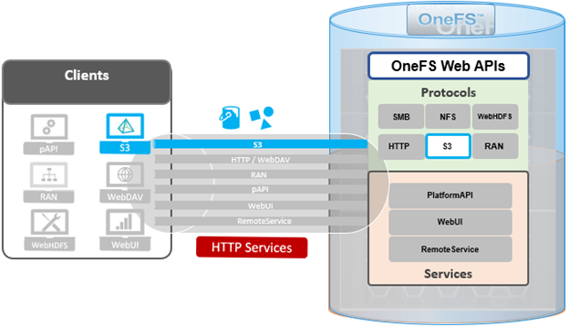
By default, the S3 service listens on port 9020 for HTTP and 9021 for HTTPS, although both these ports are easily configurable. Within a PowerScale cluster, OneFS runs on and across all nodes equally, so no one node controls or ‘masters’ the cluster and all nodes are true peers. Looking from a high-level at the components within each node, the I/O stack is split into a top layer, or initiator, and a bottom layer, or participant. This division is used as a logical model for the analysis of OneFS’ read and write paths.

At a physical-level, the CPUs and memory cache within the nodes simultaneously handle both initiator and participant tasks for I/O taking place throughout the cluster.
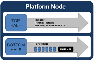
For clarity’s sake, the level of detail that includes the caches and distributed lock manager has been omitted from the above.

When a client connects to a node’s protocol head to perform a write, it is interacting with the logical ‘top half’, or initiator, of that node. Any files or objects that are written by the client are broken into smaller logical chunks, or stripes, before being written to the logical ‘bottom half’, or participant, of a node, where the storage drives reside. Failure-safe buffering (write coalescer and journal) ensures that writes are efficient and read-modify-write operations are avoided. OneFS stripes data across all nodes and protects the files, directories and associated metadata via software erasure-code or mirroring.

File and object locking allows multiple users or processes to access data via a variety of protocols concurrently and safely. Since all nodes in an PowerScale cluster operate on the same single-namespace file system simultaneously, it requires mutual exclusion mechanisms to function correctly. For reading data, this is a fairly straightforward process involving shared locks. With writes, however, things become more complex and require exclusive locking, since data must be kept consistent.

Under the hood, the ‘bottom half’ locks OneFS uses to provide consistency inside the file system (internal) are separate from the ‘top half’ protocol locks that manage concurrency across applications (external). This allows OneFS to move a file’s metadata and data blocks around while the file itself is locked by an application. This is the premise of OneFS auto-balancing, reprotecting and tiering, where the restriper does its work behind the scenes in small chunks to minimize disruption.

The OneFS distributed lock manager (DLM) marshals locks across all the nodes in a storage cluster, allowing for multiple lock types to support both file system locks as well as cluster-coherent protocol-level locks. The DLM distributes the lock data across all the nodes in the cluster. In a mixed cluster, the DLM also balances memory utilization so that the lower-power nodes are not bullied.

Every node in a cluster is a coordinator for locking resources. A coordinator is assigned to lockable resources based on a hashing algorithm, designed so that the coordinator almost always ends up on a different node than the initiator of the request. When a lock is requested for a file/object, it could be either a shared or exclusive lock. Read requests are typically serviced by shared locks, allowing multiple users to simultaneously access the resource, whereas exclusive locks constrain to just one user at any given moment, typically for writes.

Here’s an example of how different nodes could request a lock from the coordinator:
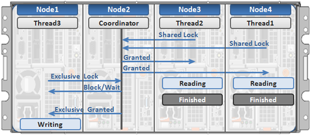
  1. Thread 1 from node 4 and thread 2 from node 3 simultaneously request a shared lock on a file from the coordinator on node 2.
  2. Since no exclusive locks exist, node 2 grants shared locks, and nodes 3 and 4 read the requested file.
  3. Thread 3 from node 1 requests an exclusive lock for the same file that’s being read by nodes 3 and 4.
  4. Nodes 3 and 4 are still reading, so the coordinator (node 2) asks thread 3 from node 1 to wait.
  5. Thread 3 from node 1 blocks until the exclusive lock is granted by the coordinator (node 2) and then completes its write operation.

As such, an S3 client can access, read, and write to an object using HTTP GET and PUT requests, while other file protocol and/or S3 clients also access the same resource. OneFS supports two methods of specifying buckets and objects in a URL:

  • Path-style requests, using the first slash-delimited component of the request-URI path. For example:

https://tme1.isilon.com:9021/bkt01/lab/object1.pdf

  • Virtual hosted-style requests, specifying a bucket via the HTTP Host header. I.e.:

https://bkt01.tme.isilon.com:9021/lab/object1.pdf

Additionally, the principal API operations that OneFS supports include:
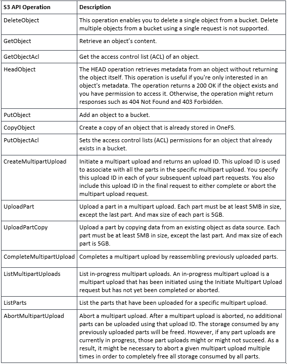
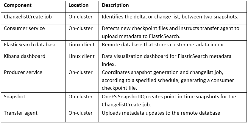
Essentially, this includes the basic bucket and object create, read, update, delete, or CRUD, operations, plus multipart upload.

As for client access, from the cluster side the general OneFS S3 operation flow can be characterized as follows:

  1. First, an S3 client or application establishes a connection to the cluster, with SmartConnect resolving the IP address with bucket name.
  2. OneFS creates a socket/listener with the appropriate TLS handling, as required.
  3. Next, OneFS (libLwHttp) receives and unmarshals the HTTP request/stream to determine the S3 request payload.
  4. Authorization and authentication is performed for bucket and object access.
  5. Next, the S3 request is queued for LwSched, which dispatches the work with the appropriate threading mode.
  6. The S3 protocol driver handles the operational logic and calls the IO manager (Lwio).
  7. Lwio manages any audit filter driver activity before and after the operation, while FSD (file system driver) handles the file system layer access.
  8. Finally, the S3 protocol driver creates an HTTP response with its operation result, which is returned to the S3 client via libLwHttp.
  9. Then back to step 3 for the next HTTP request, etc.

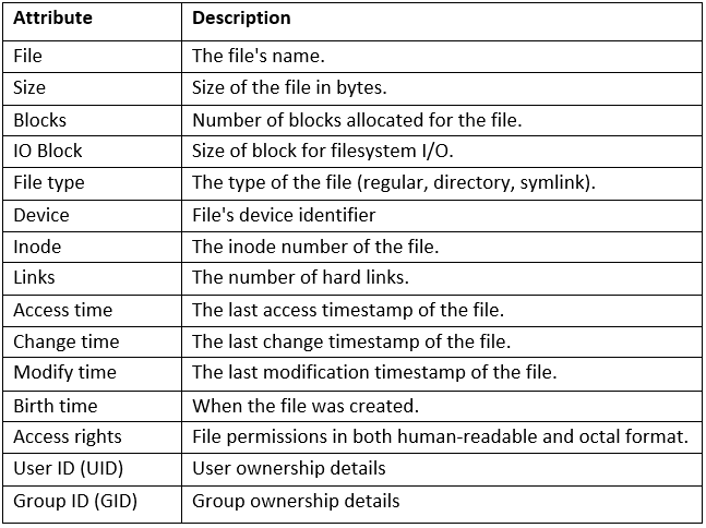
If a client HTTP request is invalid, or goes awry, OneFS follows the general AWS S3 error codes format – albeit with modifications to remove any AWS-specific info. The OneFS S3 implementation also includes some additional error codes for its intrinsic behaviors. These include:
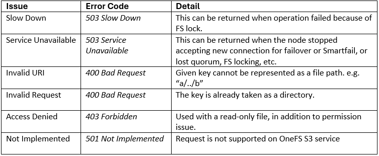
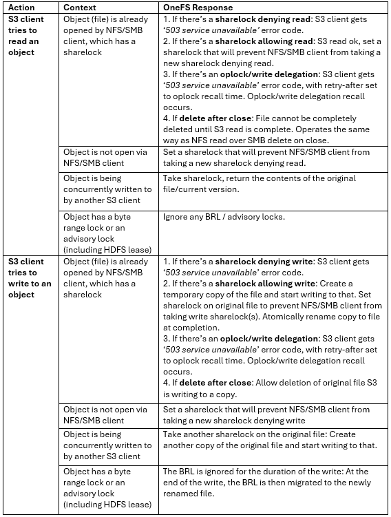
So how do things work when clients try to simultaneous access the same file/object on a cluster via both file and object protocols? Here’s the basic flow describing OneFS cross-protocol locking:
OneFS FIPS-compliant SDPM Journal

The new OneFS 9.10 release delivers an important data-at-rest encryption (DARE) security enhancement for the PowerScale F-series platforms. Specifically, the OneFS software defined persistent memory (SDPM) journal now supports self-encrypting drives, or SEDs, satisfying the criteria for FIPS 140-3 compliance.

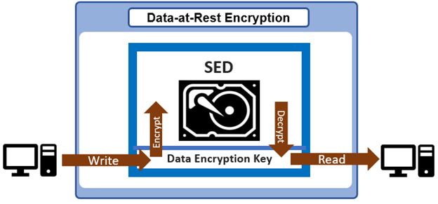
SEDs are secure storage devices which transparently encrypt all on-disk data using an internal key and a drive access password. OneFS uses nodes populated with SED drives in to provide data-at-rest encryption, thereby preventing unauthorized access data access.

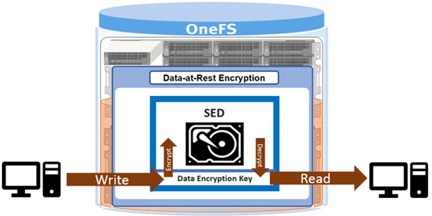
All data that is written to a DARE PowerScale cluster is automatically encrypted the moment it is written and decrypted when it is read. Securing on-disk data with cryptography ensures that the data is protected from theft, or other malicious activity, in the event drives or nodes are removed from a cluster.

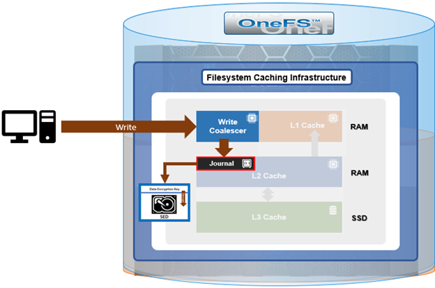
The OneFS journal is among the most critical components of a PowerScale node. When the OneFS writes to a drive, the data goes straight to the journal, allowing for a fast reply. OneFS uses journaling to ensure consistency across disks locally within a node and also disks across nodes.

Here’s how the journal fits into the general OneFS caching hierarchy:

Block writes go to the journal prior to being written to disk, and a transaction must be marked as ‘committed’ in the journal before returning success to the file system operation. Once the transaction is committed, the change is guaranteed to be stable. If the node happened to crash or lose power, the changes would still be applied from the journal at mount time via a ‘replay’ process. As such, the journal is battery-backed in order to be available after a catastrophic node event such as a data center power outage.

Operating primarily at the physical level, the journal stores changes to physical blocks on the local node. This is necessary because all initiators in OneFS have a physical view of the file system, and therefore issue physical read and write requests to remote nodes. The OneFS journal supports both 512byte and 8KiB block sizes of 512 bytes for storing written inodes and blocks respectively. By design, the contents of a node’s journal are only needed in a catastrophe, such as when memory state is lost.

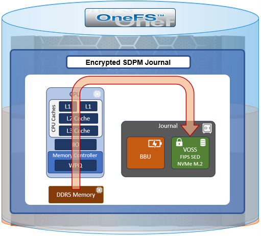
Under the hood. the current PowerScale F-series nodes use an M.2 SSD in conjunction with OneFS’ SDPM solution to provide persistent storage for the file system journal.

This is in contrast to previous generation platforms, which used NVDIMMs.

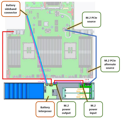
The SDPM itself comprises two main elements:

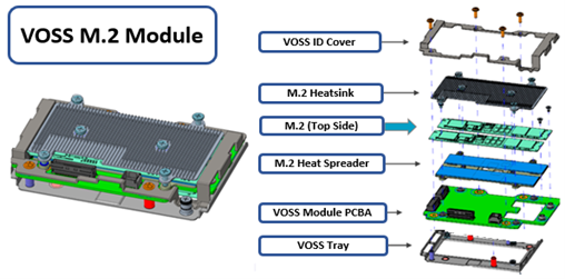
While the BBU is self-contained, the M.2 NVMe vault is housed within a VOSS module, and both components are easily replaced if necessary.

This new OneFS 9.10 functionality enables an encrypted, FIPS compliant, M.2 SSD to be used as the back-end storage for the journal’s persistent memory region. This allows the journal in an F-series to This M.2 drive is also referred to as the ‘vault’ drive, and it sits atop the ‘vault optimized storage subsystem’ or VOSS module, along with the journal battery, etc.

This new functionality enables the transparent use of the M.2 FIPS drive, securing it in tandem with the other FIPS data PCIe drives in the node. This feature also paves the way for requiring specifically FIPS 140-3 drives across the board.

So looking a bit deeper, this new SDMP enhancement for SED nodes uses a FIPS 140-3 certified M.2 SSD within the VOSS module, providing the persistent memory for the PowerScale all-flash F-series platforms.

It also builds upon coordination or BIOS features and functions, coordinating with iDRAC and OneFS coordination with iDRAC itself through the host interface, or HOSA.

And secondarily, this FIPS SDPM feature is instrumental in delivering the SED-3 security level for the F-series nodes. The redefined OneFS SED FIPS framework was discussed at length in the previous article in this series, and the SED-3 level requires FIPS 140-3 compliant drives across the board (ie. for both data storage and journal).

Under the hood, the VOSS drive is secured by iDRAC. iDRAC itself has both a local key manager, or IKLM, function and the secure enterprise key manager, or SEKM. OneFS communicates with these key managers via the HOSA and the Redfish passthrough interfaces, and configures the VOSS drive during node configuration time. Beyond that, OneFS also tears down the VOSS drive the same way it would tear down the storage drives during a node reformat operation.

As we saw in the previous blog article, there are now three levels of self-encrypting drives or SEDs in OneFS 9.10, in addition to the standard ISE (instant secure erase) drives:

  • SED level 1, previously known as SED non-FIPS.
  • SED level 2, which was formerly FIPS 140-2.
  • SED level 3, which denotes FIPS 140-3 compliance.

Beyond that, the existing behavior around security of nodes with regards to drive capability and the existing OneFS logic that prevents lesser security nodes from joining higher security clusters. This basic restriction is not materially changed in 9.10, but simply a new higher tier of security, the SED-3 tier, is added. So a cluster running comprising SED-3 nodes running OneFS 9.10 would only disallow any lesser security nodes from joining.

Specifically, the SED-3 designation requires FIPS 140-3 data drives as well as a FIPS 140-3 VOSS drive within the SDMP VOSS module. The presence of incorrect drives would result in ‘wrong type’ errors, the same as with pre 9.10 behavior. So if a node is built with the incorrect VOSS drive, or OneFS is unable to secure it, that node will fail a journal healthcheck during node boot and be automatically blocked from joining the cluster.

SED-3 compliance not only requires the drives to be secure, but actively monitored. OneFS uses its ‘hardware mon’ utility to monitor a node’s drives for correct security state, as well as checking for any unexpected state transitions. If hardware monitor detects any of these, it will trigger a CELOG alert and bring the node down into read-only state. So if a SED-3 node is in read-write state, this indicates it’s fully functional and all is good.

The ‘isi status’ CLI command has a ‘SED compliance level’ parameter which report’s the node’s level, such as SED-3. Alternatively, the ‘isi_psi_tool’ CLI utility can provide more detail on the required compliance level of the data and VOSS drives themselves, as well as node type, etc.

The OneFS hardware monitor CLI utility (isi_hwmon) can be used to check the encryption state of the VOSS drive, and the encryption state values are:

  • Unlocked: Safe state, properly secured. Unlocked indicates that iDRAC has authenticated/unlocked VOSS for SDPM read/write usage.
  • Locked: Degraded state. Secured but not accessible. VOSS drive is not available for SDPM usage.
  • Unencrypted: Degraded state. Not secured.
  • Foreign: Degraded state. iLKM is unable to authenticate. Missing Key/PIN or secured by foreign entity.

As such, only ‘unlocked’ represents a healthy state. The other three states (locked, unencrypted, and foreign) indicate an issue, and will result in a read-only node.

OneFS Data-at-rest Encryption and FIPS Compliance

On the security front, the new OneFS 9.10 release’s payload includes a refinement of the compliance levels for self-encrypting drives within a PowerScale cluster. But before we get into it, first a quick refresher on OneFS Data-at-Rest Encryption, or DARE, and FIPS compliance.

Within the IT industry, compliance with the Federal information processing standards (FIPS), denotes that a product has been certified to meet all the necessary security requirements, as defined by the National institute of standards and technology, or NIST.

A FIPS certification is not only mandated by federal agencies and departments, but is recognized globally as a hallmark of security certification. For organizations that store sensitive data, a FIPS certification may be required based on government regulations or industry standards. As companies opt for drives with a FIPS certification, they are ensured that the drives meet stringent regulatory requirements. FIPS certification is provided through the Cryptographic Module Validation Program (CMVP), which ensures that products conform to the FIPS 140 security requirements.

Data-At-Rest Encryption (DARE) is a requirement for federal and industry regulations ensuring that data is encrypted when it is stored. Dell PowerScale OneFS provides DARE through self-encrypting drives (SEDs) and a key management system. The data on a SED is encrypted, preventing a drive’s data from being accessed if the SED is stolen or removed from the cluster.

Data at rest is inactive data that is physically stored on persistent storage. Encrypting data at rest with cryptography ensures that the data is protected from theft if drives or nodes are removed from a PowerScale cluster. Compared to data in motion, which must be reassembled as it traverses network hops, data at rest is of interest to malicious parties because the data is a complete structure. The files have names and require less effort to understand when compared to smaller packetized components of a file.

However, because of the way OneFS lays out data across nodes, extracting data from a drive that’s been removed from a PowerScale cluster is not a straightforward process – even without encryption. Each data stripe is composed of data bits. Reassembling a data stripe requires all the data bits and the parity bit.

PowerScale implements DARE by using self-encrypting drives (SEDs) and AES 256-bit encryption keys. The algorithm and key strength meet the National Institute of Standards and Technology (NIST) standard and FIPS compliance. The OneFS management and system requirements of a DARE cluster are no different from standard clusters.

Note that the recommendation is for a PowerScale DARE cluster to solely comprise self-encrypting drive (SED) nodes. However, a cluster mixing SED nodes and non-SED nodes is supported during its transition to an all-SED cluster.

Once a cluster contains a SED node, only SED nodes can then be added to the cluster. While a cluster contains both SED and non-SED nodes, there is no guarantee that any particular piece of data on the cluster will, or will not, be encrypted. If a non-SED node must be removed from a cluster that contains a mix of SED and non-SED nodes, it should be replaced with an SED node to continue the evolution of the cluster from non-SED to SED. Adding non-SED nodes to an all-SED node cluster is not supported. Mixing SED and non-SED drives in the same node is not supported.

A SED drive provides full-disk encryption through onboard drive hardware, removing the need for any additional external hardware to encrypt the data on the drive. As data is written to the drive, it is automatically encrypted, and data read from the drive is decrypted. A chipset in the drive controls the encryption and decryption processes. An onboard chipset allows for a transparent encryption process. System performance is not affected, providing enhanced security and eliminating dependencies on system software.

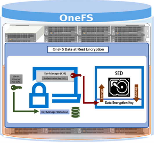
Controlling access by the drive’s onboard chipset provides security if there is theft or a software vulnerability because the data remains accessible only through the drive’s chipset. At initial setup, an SED creates a unique and random key for encrypting data during writes and decrypting data during reads. This data encryption key (DEK) ensures that the data on the drive is always encrypted. Each time data is written to the drive or read from the drive, the DEK is required to encrypt and decrypt the data,. If the DEK is not available, data on the SED is inaccessible, rendering all data on the drive unreadable.

The standard SED encryption is augmented by wrapping the DEK for each SED in an authentication key (AK). As such, the AKs for each drive are placed in a key manager (KM) which is stored securely in an encrypted database, the key manager database (KMDB), further preventing unauthorized access. The KMDB is encrypted with a 256-bit universal key (UK) as follows:

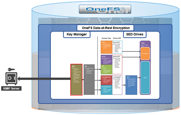
OneFS also supports an external key manager by using a key management interoperability protocol (KMIP)-compliant key manager server. In this case, the universal key (UK) is stored in a KMIP-compliant server.

Note, however, that PowerScale OneFS releases prior to OneFS 9.2 retain the UK internally on the node.

Further protecting the KMDB, OneFS 9.5 and later releases also provide the ability to rekey the UK – either on-demand or per a configured schedule. This applies to both UKs that are stored on-cluster or on an external KMIP server.

The authentication key (AK) is unique to each SED, and this ensures that OneFS never knows the DEK. If there is a drive theft from a PowerScale node, the data on the SED is useless because the trifecta of the UK, AK, and the DEK, are all required to unlock the drive. If an SED is removed from a node, OneFS automatically deletes the AK. Conversely, when a new SED is added to a node, OneFS automatically assigns a new AK.

With the PowerScale H and A-series chassis-based platforms, the KMDB is stored in the node’s NVRAM, and a copy is also placed in the partner node’s NVRAM. For PowerScale F-series nodes, the KMDB is stored in the trusted platform module (TPM). Using the KM and AKs ensures that the DEKs never leave the SED boundary, as required for FIPS compliance. In contrast, legacy Gen 5 Isilon nodes store the KMDB on both compact flash drives in each node.

The key manager uses a FIPS-validated crypto when the STIG hardening profile is applied to the cluster.

The KM and KMDB are entirely secure and cannot be compromised because they are not accessible by any CLI command or script. The KMDB only stores the local drives’ AKs in Gen 5 nodes, and buddy node drives in Gen 6 nodes. On PowerEdge based nodes, the KMDB only stores the AKs of local drives. The KM also uses its encryption not to store the AKs in plain text.

OneFS external key management operates by storing the 256-bit universal key (UK) in a key management interoperability protocol (KMIP)-compliant key manager server.

In order to store the UK on a KMIP server, a PowerScale cluster requires the following:
  • OneFS 9.2 (or later) cluster with SEDs
  • KMIP-compliant server:
  • KMIP 1.2 or later
  • KMIP storage array 1.0 or later with SEDS profile
  • KMIP server host/port information
  • 509 PKI for TLS mutual authentication
  • Certificate authority bundle
  • Client certificate and private key
  • Administrator privilege: ISI_PRIV_KEY_MANAGER
  • Network connectivity from each node in the cluster to the KMIP server using an interface in a statically assigned network pool; for SED drives to be unlocked, each node in the cluster contacts the KMIP server at bootup to obtain the UK from the KMIP server, or the node bootup fails
  • Not All Nodes On Network (NANON) and Not all Nodes On All Networks (NANOAN) clusters are not supported

As mentioned earlier, the drive encryption levels are clarified in OneFS 9.10. There are three levels of self-encrypting drives, each now designated with a ‘SED-‘ prefix, in addition to the standard ISE (instant secure erase) drives.

These OneFS 9.10 designations include SED level 1, previously known as SED non-FIPS, SED level 2, which was formerly FIPS 140 dash 2, and SED level 3, which denotes FIPS 140-3 compliance.

Confirmation of a node’s SED level status can be verified via the ‘isi status’ CLI command output. For example, the following F710 node output indicates full SED level 3 (FIPS 140-3) compliance:

# isi status --node 1

Node LNN:         1

Node ID:          1

Node Name:       tme-f710-1-1

Node IP Address: 10.1.10.21

Node Health:            OK

Node Ext Conn:    C

Node SN:          DT10004

SED Compliance Level: SED-3

Similarly, the SED compliance level can be queried for individual drives with the following CLI syntax:

# isi device drive view [drive_bay_number] | grep -i compliance
SED Compliance Level: SED-FIPS-140-2

Additionally, the ‘isi_psi_tool’ CLI utility can provide more detail on the required compliance level of the data and journal drives, as well as node type, etc. For example, the SED-3 SSDs in this F710 node:

# /usr/bin/isi_hwtools/isi_psi_tool -v

{

"DRIVES": [

"DRIVES_10x3840GB(pcie_ssd_sed3)"

],

"JOURNAL": "JOURNAL_SDPM",

"MEMORY": "MEMORY_DIMM_16x32GB",

"NETWORK": [

"NETWORK_100GBE_PCI_SLOT1",

"NETWORK_100GBE_PCI_SLOT3",

"NETWORK_1GBE_PCI_LOM"

],

"PLATFORM": "PLATFORM_PE",

"PLATFORM_MODEL": "MODEL_F710",

"PLATFORM_TYPE": "PLATFORM_PER660"

}

Beyond that, the existing behavior around security of nodes with regards to drive capability and the existing OneFS logic that prevents lesser security nodes from joining higher security clusters is retained. As such, the supported SED node matrix in OneFS 9.10 is as follows:

So, for example, a OneFS 9.10 cluster comprising SED-3 nodes would prevent any lesser security nodes (ie. SED-2 or below) from joining.

In addition to FIPS 140-3 data drives, the OneFS SED-3 designation also requires FIPS 140-3 compliant flash media for the OneFS filesystem journal. The presence of any incorrect drives (data or journal) in a  node will result in ‘wrong type’ errors, the same as with pre-OneFS 9.10 behavior. Additionally, FIPS 104-3 (SED-3) not only requires a node’s drives to be secure, but also actively monitored. ‘Hardware mon’ is used within OneFS to monitor drive state, checking for correct security state as well as any unexpected state transitions. If hardware monitor detects any of these, it will trigger a CELOG alert and bring the node into read-only state. This will be covered in more detail in the next blog post in this series.

PowerScale InsightIQ 5.2

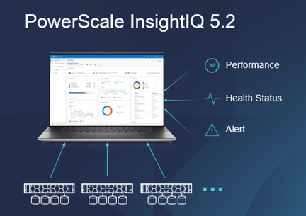
It’s been a prolific week for PowerScale! Hot on the heels of the OneFS 9.10 launch comes the unveiling of the new InsightIQ 5.2 release. InsightIQ delivers powerful performance monitoring and reporting functionality, helping maximize PowerScale cluster performance. This includes advanced analytics to optimize applications, correlate cluster events, and accurately forecast future storage needs.

So what new goodness does the InsightIQ 5.2 release deliver? Added functionality includes expanded ecosystem support, enhanced reporting, and streamlined upgrade and migration.

The InsightIQ (IIQ) ecosystem is expanded in 5.2 to now include Red Hat Enterprise Linux (RHEL) versions 9.4 and 8.10. This allows customers who are running current RHEL code to use InsightIQ 5.x to monitor the latest OneFS versions. Additionally, InsightIQ Simple can now be installed on VMware Workstation 17, allowing IIQ 5.2 to be deployed on non-production lab environments for trial or demo purposes – without incurring a VMware charge.

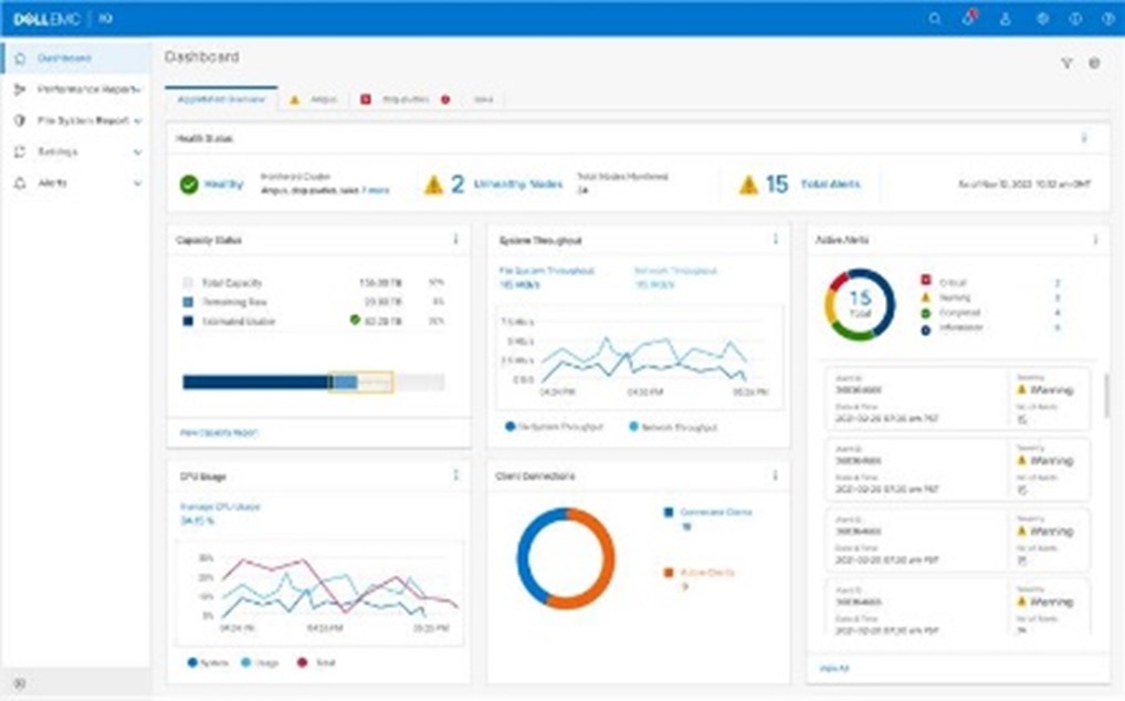
On the reporting front, dashboard and report visibility has been enhanced to allow a greater number of clusters to be viewed via the dashboard’s performance overview screen. This enables users to easily compare a broad array of multi-cluster metrics on a single pane without the need for additional scrolling and navigation.

Additionally, IIQ 5.2 also expands the maximum and minimum range for a sample point across all performance reports. This allows cluster administrators to more easily identify a potential issue with the full fidelity of metrics displayed, whereas previously down sampling to an average value may have masked an anomaly.

Support and serviceability-wise, IIQ 5.2 brings additional upgrade and migration functionality. Specifically, cluster admins can perform simple, non-disruptive in-place upgrades from IIQ 5.1 to IIQ 5.2. Additionally, IIQ 4.4.1 instances can also now be directly migrated to the new IIQ 5.2 release without the need to export or import any data, or reconfiguring any settings.

Function Attribute Description
OS Support Simple ecosystem support InsightIQ Simple 5.2.0 can be deployed on the following platforms:

·         VMware virtual machine running ESXi version 7.0U3 or 8.0U3

·         VMware Workstation 17 (free version) InsightIQ Simple 5.2.0 can monitor PowerScale clusters running OneFS versions 9.3 through 9.10, excluding 9.6.

Scale ecosystem support InsightIQ Scale 5.2.0 can be deployed on Red Hat Enterprise Linux versions 8.10 or 9.4 (English language versions). InsightIQ Scale 5.2.0 can monitor PowerScale clusters running OneFS versions 9.3 through 9.10, excluding 9.6.
Upgrade In-place upgrade from InsightIQ 5.1.x to 5.2.0 The upgrade script supports in-place upgrades from InsightIQ 5.1.x.
Direct database migration from InsightIQ 4.4.1 to InsightIQ 5.2.0 Direct data migration from an InsightIQ 4.4.1 database to InsightIQ 5.2.0 is supported.
Reporting Maximum and minimum ranges on all reports All live Performance Reports display a light blue zone that indicates the range of values for a metric within the sample length. The light blue zone is shown regardless of whether any filter is applied. With this enhancement, users can observe trends in values on filtered graphs.
More graphs on a page Reports are redesigned to maximize the number of graphs that can appear on each page.

·         Excess white space is eliminated.

·         The report parameters section collapses when the report is run. The user can expand it manually.

·         Graph heights are decreased when possible.

·         Page scrolling occurs while the collapsed parameters section remains fixed at the top.

User interface What’s New dialog All InsightIQ users can view a brief introduction to new functionality in the latest release of InsightIQ. Access the dialog from the banner area of the InsightIQ web application. Click About > What’s New.
Compact cluster performance view on the Dashboard The Dashboard is redesigned to improve usability.

·         Summary information for six clusters appears in the initial Dashboard view. A sectional scrollbar controls the view for additional clusters.

·         The capacity section has its own scrollbar.

·         The navigation side bar is collapsible into space-saving icons. Use the << icon at the bottom of the side bar to collapse it.

Meanwhile, the new InsightIQ 5.2 code is available on the Dell Support site, allowing both installation of and upgrade to this new release.