The CAP theorem states that a distributed system cannot simultaneously guarantee consistency, availability, and partition tolerance. This means that, when faced with a network partition, a choice must be made between consistency and availability. OneFS does not compromise on consistency, so a mechanism is required to manage a cluster’s transient state.
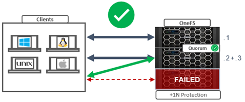
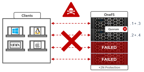
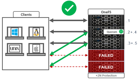
In order for a cluster to properly function and accept data writes, a quorum of nodes must be active and responding. A quorum is defined as a simple majority: a cluster with N nodes must have ⌊N/2⌋+1 nodes online in order to allow writes.
OneFS uses a quorum to prevent ‘split-brain’ conditions that can be introduced if the cluster should temporarily divide into two clusters. By following the quorum rule, the architecture guarantees that regardless of how many nodes fail or come back online, if a write takes place, it can be made consistent with any previous writes that have ever taken place.
Within OneFS, quorum is a property of the group management protocol (GMP) group which helps enforce consistency across node disconnects. As we saw in the previous article, since both nodes and drives in OneFS may be readable, but not writable, OneFS actually has two quorum properties:
Read quorum is represented by ‘efs.gmp.has_quorum’ and write quorum by ‘efs.gmp.has_super_block_quorum’. For example:
# sysctl efs.gmp.has_quorum

efs.gmp.has_quorum: 1

# sysctl efs.gmp.has_super_block_quorum

efs.gmp.has_super_block_quorum: 1
The value of ‘1’ for each of the above confirms that the cluster currently has both read and write quorum respectively.
In OneFS, a group is basically a list of nodes and drives which are currently participating in the cluster. Any nodes that are not in a cluster’s main quorum group form multiple groups.. As such, the main purpose of the OneFS Group Management Protocol (GMP) is to help create and maintain a group of synchronized nodes. Having a consistent view of the cluster state is critical, since initiators need to know which node and drives are available to write to, etc.
The group of nodes with quorum is referred to as the ‘majority side’. Conversely, any node group without quorum is termed a ‘minority side’.
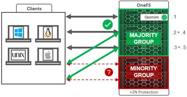
There can only be one majority group, but there may be multiple minority groups. A group which has one or more components in a failed state is called ‘degraded’. The degraded property is frequently used as an optimization to avoid checking the capabilities of each component. The term ‘degraded’ is also used to refer to components without their maximum capabilities.
The following table lists and describes that various terminology associated with OneFS groups and quorum.
| Term |
Definition |
| Degraded |
A group which has one or more components in a failed state is called ‘degraded’. |
| Dynamic Aspect |
The dynamic aspect refers to the state (and health) of nodes and drives which may change. |
| GMP |
Group Management Protocol, which helps create and maintain a group of synchronized nodes. Having a consistent view of the cluster state is critical, since initiators need to know which node and drives are available to write to, etc |
| Group |
A group is a given set of nodes which have synchronized state. |
| Majority side |
A group of nodes with quorum is referred to as the ‘majority side’. By definition, there can only be one majority group. |
| Minority side |
Any group of nodes without quorum is a ‘minority side’. There may be multiple minority groups. |
| Quorum group |
A group of nodes with quorum, referred to as the ‘majority side’ |
| Static Aspect |
The static aspect is the composition of the cluster, which is stored in the array.xml file. |
Under normal operating conditions, every node and its disks are part of the current group, which can be shown by running sysctl efs.gmp.group on any node of the cluster. For example, the complex group output from a 93 node cluster:
# sysctl efs.gmp.group
efs.gmp.group: <d70af9> (93) :{ 1-14:0-14, 15:0-13, 16-19:0-14, 20:0-13, 21-28,30-33:0-14, 34:0-4,6-10,12-14, 35-36:0-14, 37-48:0-19, 49-60:0-14, 61-62:0-13, 63-81:0-14, 82:0-7,9-14, 83-87:0-14, 88:0-13, 89-91:0-14, 92:0-1,3-14, down: 29, soft_failed: 29, read_only: 29, smb: 1-28,30-92, nfs: 1-28,30-92, swift: 1-28,30-92, all_enabled_protocols: 1-28,30-92, isi_cbind_d: 1-28,30-92, lsass: 1-28,30-92, s3: 1-28,30-92, external_connectivity: 1-28,30-92 }
As can be seen above, protocol and external network participation is also reported, in addition to the overall state of the nodes and drives in the group,.
For more verbose output, the efs.gmp.current_info sysctl yields extensive current GMP information.
# sysctl efs.gmp.current_info
So a quorum group, as reported by GMP, consists of two parts:
| Group component |
Description |
| Sequence number |
Provides identification for the group |
| Membership list |
Describes the group |
The sequence number in the example above is: <d70af9>
Next, the membership list shows the group members within brackets. For example, { 1-4:0-14 … } represents a four node pool, with Array IDs 1 through 4. Each node contains 15 drives, numbered zero through 14.
- The numbers before the colon in the group membership list represent the participating Array IDs.
- The numbers after the colon represent Drive IDs.
Note that node IDs differ from Logical Node Numbers (LNNs), the node numbers that occur within node names, and displayed by isi stat.
GMP distributes a variety of state information about nodes and drives, from identifiers to usage statistics. The most fundamental of these is the composition of the cluster, or ‘static aspect’ of the group, which is stored in the array.xml file. The array.xml file also includes info such as the ID, GUID, and whether the node is diskless or storage, plus attributes not considered part of the static aspect, such as internal IP addresses.
Similarly, the state of a node’s drives is stored in the drives.xml file, along with a flag indicating whether the drive is an SSD. Whereas GMP manages node states directly, drive states are actually managed by the ‘drv’ module, and broadcast via GMP. A significant difference between nodes and drives is that for nodes, the static aspect is distributed to every node in the array.xml file, whereas drive state is only stored locally on a node. The array.xml information is needed by every node in order to define the cluster and allow nodes to form connections. In contrast, drives.xml is only stored locally on a node. When a node goes down, other nodes have no method to obtain the drive configuration of that node. Drive information may be cached by the GMP, but it is not available if that cache is cleared.
Conversely, ‘dynamic aspect’ refers to the state of nodes and drives which may change. These states indicate the health of nodes and their drives to the various file system modules – plus whether or not components can be used for particular operations. For example, a soft-failed node or drive should not be used for new allocations. These components can be in one of seven states:
| Node State |
Description |
| Dead |
The component is not allowed to come back to the UP state and should be removed. |
| Down |
The component is not responding. |
| Gone |
The component has been removed. |
| Read-only |
This state only applies to nodes. |
| Soft-failed |
The component is in the process of being removed. |
| Stalled |
A drive is responding slowly. |
| Up |
The component is responding. |
Note that a node or drive may go from ‘down, soft-failed’ to ‘up, soft-failed’ and back. These flags are persistently stored in the array.xml file for nodes and the drives.xml file for drives.
Group and drive state information allows the various file system modules to make timely and accurate decisions about how they should utilize nodes and drives. For example, when reading a block, the selected mirror should be on a node and drive where a read can succeed (if possible). File system modules use the GMP to test for node and drive capabilities, which include:
| Capability |
Description |
| Readable |
Drives on this node may be read. |
| Restripe From |
Move blocks away from the node. |
| Writable |
Drives on this node may be written to. |
Access levels help define ‘as a last resort’ with states for which access should be avoided unless necessary. The access levels, in order of increased access, are as follows:
| Access Level |
Description |
| Modify stalled |
Allows writing to stalled drives. |
| Never |
Indicates a group state never supports the capability. |
| Normal |
The default access level |
| Read soft-fail |
Allows reading from soft-failed nodes and drives. |
| Read stalled |
Allows reading from stalled drives. |
Drive state and node state capabilities are shown in the following tables. As shown, the only group states affected by increasing access levels are soft-failed and stalled.
Minimum Access Level for Capabilities Per Node State
| Node States |
Readable |
Writeable |
Restripe From |
| UP |
Normal |
Normal |
No |
| UP, Smartfail |
Soft-fail |
Never |
Yes |
| UP, Read-only |
Normal |
Never |
No |
| UP, Smartfail, Read-only |
Soft-fail |
Never |
Yes |
| DOWN |
Never |
Never |
No |
| DOWN, Smartfail |
Never |
Never |
Yes |
| DOWN, Read-only |
Never |
Never |
No |
| DOWN, Smartfail, Read-only |
Never |
Never |
Yes |
| DEAD |
Never |
Never |
Yes |
Minimum Access Level for Capabilities Per Drive State
| Drive States |
Minimum Access Level to Read |
Minimum Access Level to Write |
Restripe From |
| UP |
Normal |
Normal |
No |
| UP, Smartfail |
Soft-fail |
Never |
Yes |
| DOWN |
Never |
Never |
No |
| DOWN, Smartfail |
Never |
Never |
Yes |
| DEAD |
Never |
Never |
Yes |
| STALLED |
Read_Stalled |
Modify_Stalled |
No |
OneFS depends on a consistent view of a cluster’s group state. For example, some decisions, such as choosing lock coordinators, are made assuming all nodes have the same coherent notion of the cluster.
Group changes originate from multiple sources, depending on the particular state. Drive group changes are initiated by the drv module. Service group changes are initiated by processes opening and closing service devices. Each group change creates a new group ID, comprising a node ID and a group serial number. This group ID can be used to quickly determine whether a cluster’s group has changed, and is invaluable for troubleshooting cluster issues, by identifying the history of group changes across the nodes’ log files.
GMP provides coherent cluster state transitions using a process similar to two-phase commit, with the up and down states for nodes being directly managed by the GMP. RBM or Remote Block Manager code provides the communication channel that connect devices in the OneFS. When a node mounts /ifs it initializes the RBM in order to connect to the other nodes in the cluster, and uses it to exchange GMP Info, negotiate locks, and access data on the other nodes.
When a group change occurs, a cluster-wide process writes a message describing the new group membership to /var/log/messages on every node. Similarly, if a cluster ‘splits’, the newly-formed sub-clusters behave in the same way: each node records its group membership to /var/log/messages. When a cluster splits, it breaks into multiple clusters (multiple groups). This is rarely, if ever, a desirable event. A cluster is defined by its group members. Nodes or drives which lose sight of other group members no longer belong to the same group and therefore no longer belong to the same cluster.
The ‘grep’ CLI utility can be used to view group changes from one node’s perspective, by searching /var/log/messages for the expression ‘new group’. This will extract the group change statements from the logfile. The output from this command may be lengthy, so can be piped to the ‘tail’ command to limit it the desired number of lines. For example, to get the last two group changes from the local node’s log:
# grep -i 'new group' /var/log/messages | tail -n 2

2024-03-25T16:47:22.114319+00:00 <0.4> TME1-8(id8) /boot/kernel.amd64/kernel: [gmp_info.c:2690](pid 63964="kt: gmp-drive-updat")(tid=101253) new group: <d70aac> (93) { 1-14:0-14, 15:0-13, 16-19:0-14, 20:0-13, 21-28,30-33:0-14, 34:0-4,6-10,12-14, 35-36:0-14, 37-48:0-19, 49-60:0-14, 61-62:0-13, 63-81:0-14, 82:0-7,9-14, 83-87:0-14, 88:0-13, 89-91:0-14, 92:0-1,3-14, down: 29, read_only: 29 }

2024-03-26T15:34:57.131337+00:00 <0.4> TME1-8(id8) /boot/kernel.amd64/kernel: [gmp_info.c:2690](pid 88332="kt: gmp-config")(tid=101526) new group: <d70aed> (93) { 1-14:0-14, 15:0-13, 16-19:0-14, 20:0-13, 21-28,30-33:0-14, 34:0-4,6-10,12-14, 35-36:0-14, 37-48:0-19, 49-60:0-14, 61-62:0-13, 63-81:0-14, 82:0-7,9-14, 83-87:0-14, 88:0-13, 89-91:0-14, 92:0-1,3-14, down: 29, soft_failed: 29, read_only: 29 }