In order for success with large AI model customization, inferencing, and training, GPUs require data served to them quickly and efficiently. Compute and storage must be architected and provisioned accordingly, in order to eliminate potential bottlenecks in the infrastructure.
To meet this demand, the new PowerScale multipath client driver enables performance aggregation of multiple PowerScale nodes through a single NFS mount point to one or many compute nodes. As a result, this driver, in conjunction with OneFS GPUDirect support, has enabled Dell to deliver the first Ethernet storage solution to be certified for NVIDIA’s DGX SuperPOD.
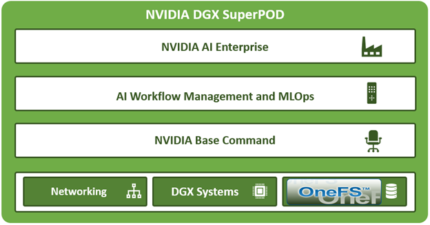
SuperPOD is an AI-optimized data center architecture that delivers the formidable computational power required to train deep learning (DL) models at scale, accelerating time to outcomes which drive future innovation.
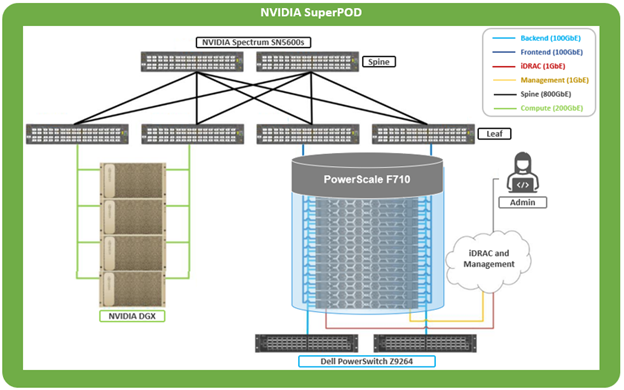
Using DGX A200, B200, or H200 GPU-based compute in concert with a PowerScale F710 clustered storage layer, NVIDIA’s SuperPOD is able to deliver groundbreaking performance.
Deployed as a fully integrated scalable system, SuperPOD is purpose-built for solving challenging computational problems across a diverse range of AI workloads. These include streamlining supply chains, building large language models, and extracting insights from petabytes of unstructured data.
The performance envelope delivered by DGX SuperPOD enables rapid multi-node training of LLMs at significant scale. This integrated approach of provisioning, management, compute, networking, and fast storage, enables a diverse system that can span data analytics, model development, and AI inferencing, right up to the largest, most complex transformer-based AI workloads, deep learning systems, and trillion-parameter generative AI models.
To drive the throughput required for larger NVIDIA SuperPOD deployments, NFS client connectivity to a PowerScale cluster needs to utilize both RDMA and nconnect, in addition to GPUDirect.
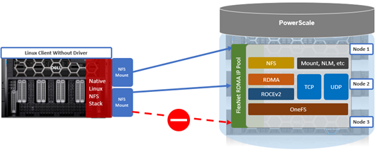
While the native Linux NFS stack supports their use, it does not allow nconnect and RDMA to be configured simultaneously.
To address this, the multipath driver permits Linux NFS clients to use RDMA in conjunction with nconnect mount options, while also increasing the maximum nconnect limit from 16 to 64 connections. Additionally, the SuperPOD solution mandates the use of the ‘localports_failover’ NFS mount option, which only works with RDMA currently.
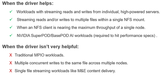
The Dell multipath client driver can be of considerable performance benefit for workloads with streaming reads and writes to and from individual high-powered servers, particularly to multiple files within a single NFS mount – in addition to SuperPOD and BasePOD AI workloads. Conversely, single file streams, and multiple concurrent writes to the same file across multiple nodes typically don’t benefit substantially from the multipath driver.
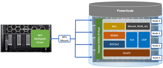
Without the multipath client driver, a single NFS mount can only route to one PowerScale storage node IP address.
By way of contrast, the multipath driver allows NFS clients to direct I/O to multiple PowerScale nodes for higher aggregate single-client throughput.
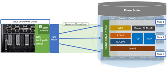
The multipath driver enables a single NFS mount point to route to multiple node IP addresses. A group of IP addresses consists of one logical NFS client with the remote endpoint (cluster) using multiple remote machines (nodes), implementing a distributed server architecture.
The principle NFS mount options of interest with the multipath client driver are:
| Mount option | Description |
| nconnect | Allows the admin to specify the number of TCP connections the client can establish between itself and the NFS server. It works with remoteports to spread load across multiple target interfaces. |
| localports | Mount option that allows a client to use its multiple NICs to multiplex I/O. |
| localports_failover | Mount option allowing transports to temporarily move from local client interfaces that are unable to serve NFS connections. |
| proto | The underlying transport protocol that the NFS mount will use. Typically, either TCP or RDMA. |
| remoteports | Mount option that allows a client to target multiple servers/ NICS to multiplex I/O. Remoteports spreads the load to multiple file handles instead of taking a single file handle to avoid thrashing on locks. |
| version | The version of the NFS protocol that is to be used. The multipath driver supports NFSv3, NFSv4.1, and NFSv4.2. Note that NFSv4.0 is unsupported. |
There are also several advanced mount options which can be useful to squeeze out some extra throughput, particularly with SuperPOD deployments. These options include ‘remoteport offsets’, which can help with loading up L1 cache, and’ spread reads and writes’, which can assist with load balancing.
The Dell multipath driver is available for download on the Dell Support Site to any customer that has OneFS entitlement:
https://www.dell.com/support/home/en-us/product-support/product/isilon-onefs/drivers
There is no license requirement for this driver, nor charge for it, and its provided as both pre-built Linux package, and customer-compliable source code. There’s a README file included with the code that provides basic instruction.
This multipath client driver runs on both physical and virtual machines, and across several popular Linux distros. The following matrix shows the currently supported variants, plus the availability of a pre-compiled driver package and/or self-compilation option.
| Linux distribution | Kernel version | Upstream driver version (minimum) | Multipath driver version | Package
available |
Self-
compile |
| OpenSUSE 15.4 | 5.14.x | 4.x | 1.x | ü | ü |
| Ubuntu 20.04 | 5.4.x | 4.x | 1.x | ü | ü |
| Ubuntu 22.04 | 5.15.x | 4.x | 1.x | ü | ü |
While the multipath driver’s major release version—1.x—is correct in the table, the second digit release number will be frequently incremented as updated versions of the multipath client driver are released.
By design, the multipath driver only supports newer and most recent versions of the popular Linux distributions. Older Linux kernel versions often do not support full NFS client functionality, particularly for the ‘–remoteports’ and/or ‘–localports’ mount configuration options. Additionally, older and end-of-life Linux versions can often present significant security risks, especially once current vulnerability patches and hotfixes are no longer being made available.
Both x86 CPU architectures and GPU-based platforms, such as the NVIDIA DGX range, are supported.
| Linux system | Processor type | Example |
| Physical | CPU | Dell PE R760 |
| Physical | GPU | Dell PE XE9680
NVIDIA DGX H100 |
| Virtual machine | CPU | VMware ESXi |
| Virtual machine | GPU | VMware vDGA |
While there is no specific NFS or OneFS core configuration required on the PowerScale cluster side for multipath driver support, there are a couple of basic prerequisites The following OneFS support matrix on the top right of this slide lays out which driver functionality is available in what release, from OneFS 9.5 to current.
| Version | NFSv3, NFSv4.1 TCP | NFSv3 RDMA | NFSv4.1 RDMA | NVIDIA SuperPOD |
| OneFS 9.5 | Yes | Yes | No | No |
| OneFS 9.7 | Yes | Yes | Yes | No |
| OneFS 9.9 | Yes | Yes | Yes | Yes |
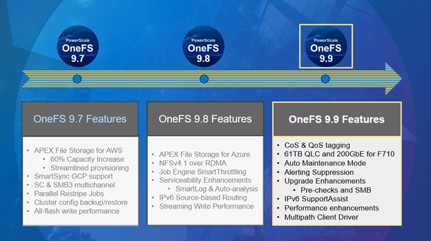
Also note that OneFS 9.9 is required for any NVIDIA SuperPOD deployments, because there are some performance optimizations in 9.9 specifically for that platform.
Additionally, both the dynamic and static network pools can be configured on the cluster for use with the multipath driver. If F710 nodes are being deployed in the cluster, OneFS 9.7 or later is required.
Note that when deploying an NVIDIA SuperPOD or BasePOD solution, the reference architecture mandates a PowerScale cluster composed of F710 all-flash nodes running OneFS 9.9 or later.
For a Linux client to successfully connect to a PowerScale cluster using the multipath driver it currently must be running one of the following Linux flavors:
| Supported Linux Distribution | Kernel Version |
| OpenSUSE 15.4 | 5.14.x |
| Ubuntu 20.04 | 5.4.x |
| Ubuntu 22.04 | 5.15.x |
By design, the multipath driver only supports newer and most recent versions of the popular Linux distributions. Older Linux kernels often don’t include full NFS client functionality, particularly for the ‘–remoteports’ and ‘–localports’ mount options. You will also likely notice the conspicuous absence of Red Hat Enterprise Linux from this matrix. However, engineering do anticipate supporting both RHEL 8 and 9 in a near-future version.
There are also a couple of additional client prerequisites that must be met:
- If RDMA is being configured, the client must contain an RDMA-capable Ethernet NIC, such as the Mellanox CX series.
- The Linux client should have the ‘trace-cmd’ package installed, along with NFS client related packages.
In the next article in this series, we’ll take a look at the specifics of the multipath driver binary package installation.