OneFS and Designing Large Clusters

Received a couple of recent enquiries around how to best accommodate big, unstructured datasets and varied workloads, so it seemed like an interesting topic to cover in a blog article.

Essentially, when it comes to designing and scaling large PowerScale clusters for large quantities and growth rates of data, there are some key tenets to bear in mind. These include:

  • Strive for simplicity
  • Plan ahead
  • Just because you can doesn’t necessarily mean you should

Distributed systems tend to be complex by definition, and this is amplified at scale. OneFS does a good job of simplifying cluster administration and management, but a solid architectural design and growth plan is crucial. Because of its single, massive volume and namespace, OneFS is viewed by many as a sort of ‘storage Swiss army knife’. Left unchecked, this methodology can result in unnecessary complexities as a cluster scales. As such, decision making that favors simplicity is key.

Despite OneFS’ extensibility, allowing a PowerScale system to simply grow organically into a large cluster often results in various levels of technical debt. In the worst case, some issues may have grown so large that it becomes impossible to correct the underlying cause. This is particularly true in instances where a small cluster is initially purchased for an archive or low performance workload and with a bias towards cost optimized storage. As the administrators realize how simple and versatile their clustered storage environment is, more applications and workflows are migrated to OneFS. This kind of haphazard growth, such as morphing from a low-powered, near-line platform into something larger and more performant, can lead to all manner of scaling challenges. However, compromises, living with things, or fixing issues that could have been avoided can usually be mitigated by starting out with a scalable architecture, workflow and expansion plan.

Beginning the process with a defined architecture, sizing and expansion plan is key. What do you anticipate the cluster, workloads, and client access levels will look like in six months, one year, three years, or five years? How will you accommodate the following as the cluster scales?

  • Contiguous rack space for expansion
  • Sufficient power & Cooling
  • Network infrastructure
  • Backend switch capacity
  • Availability SLAs
  • Serviceability and spares plan
  • Backup and DR plans
  • Mixed protocols
  • Security, access control, authentication services, and audit
  • Regulatory compliance and security mandates
  • Multi-tenancy and separation
  • Bandwidth segregation – client I/O, replication, etc.
  • Application and workflow expansion

There are really two distinct paths to pursue when initially designing an OneFS clustered storage architecture for a large and/or rapidly growing environment – particularly one that includes a performance workload element to it. These are:

  • Single Large Cluster
  • Storage Pod Architecture

A single large, or extra-large, cluster is often deployed to support a wide variety of workloads and their requisite protocols and performance profiles – from primary to archive – within a single, scalable volume and namespace. This approach, referred to as a ‘data lake architecture’, usually involves more than one style of node.

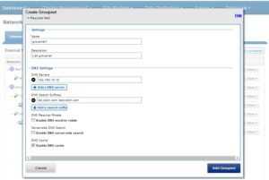
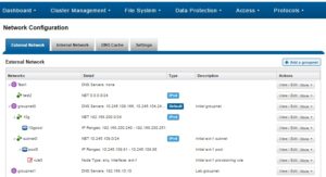
OneFS can support up to fifty separate tenants in a single cluster, each with their own subnet, routing, DNS, and security infrastructure. OneFS’ provides the ability to separate data layout with SmartPools, export and share level segregation, granular authentication and access control with Access Zones, and network partitioning with SmartConnect, subnets, and VLANs.

Furthermore, analytics workloads can easily be run against the datasets in a single location and without the need for additional storage and data replication and migration.

For the right combination of workloads, the data lake architecture has many favorable efficiencies of scale and centralized administration.

Another use case for large clusters is in a single workflow deployment, for example as the content repository for the asset management layer of a content delivery workflow. This is a considerably more predictable, and hence simpler to architect, environment that the data lake.

Often, as in the case of a MAM for streaming playout for example, a single node type is deployed. The I/O profile is typically heavily biased towards streaming reads and metadata reads, with a smaller portion of writes for ingest.

There are trade-offs to be aware of as cluster size increases into the extra-large cluster scale. The larger the node count, the more components are involved, which increases the likelihood of a hardware failure. When the infrastructure becomes large and complex enough, there’s more often than not a drive failing or a node in an otherwise degraded state. At this point, the cluster can be in a state of flux such that composition, or group, changes and drive rebuilds/data re-protects will occur frequently enough that they can start to significantly impact the workflow.

Higher levels of protection are required for large clusters, which has a direct impact on capacity utilization. Also, cluster maintenance becomes harder to schedule since many workflows, often with varying availability SLAs, need to be accommodated.

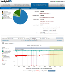
Additional administrative shortcomings that also need to be considered when planning on an extra-large cluster include that InsightIQ only supports monitoring clusters of up to eighty nodes and the OneFS Cluster Event Log (CELOG) and some of the cluster WebUI and CLI tools can prove challenging at an extra-large cluster scale.

That said, there can be wisdom in architecting a clustered NAS environment into smaller buckets and thereby managing risk for the business vs putting the ‘all eggs in one basket’. When contemplating the merits of an extra-large cluster, also consider:

  • Performance management,
  • Risk management
  • Accurate workflow sizing
  • Complexity management.

A more practical approach for more demanding, HPC, and high-IOPS workloads often lies with the Storage Pod architecture. Here, design considerations for new clusters revolve around multiple (typically up to 40 node) homogenous clusters, with each cluster itself acting as a fault domain – in contrast to the monolithic extra-large cluster described above.

Pod clusters can easily be tailored to the individual demands of workloads as necessary. Optimizations per storage pod can include size of SSDs, drive protection levels, data services, availability SLAs, etc. In addition, smaller clusters greatly reduce the frequency and impact of drive failures and their subsequent rebuild operations. This, coupled with the ability to more easily schedule maintenance, manage smaller datasets, simplify DR processes, etc, can all help alleviate the administrative overhead for a cluster.

A Pod infrastructure can be architected per application, workload, similar I/O type (ie. streaming reads), project, tenant (ie. business unit), availability SLA, etc. This pod approach has been successfully adopted by a number of large PowerScale customers in industries such as semiconductor, automotive, life sciences, and others with demanding performance workloads.

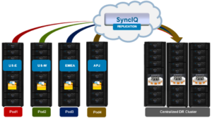
This Pod architecture model can also fit well for global organizations, where a cluster is deployed per region or availability zone. An extra-large cluster architecture can be usefully deployed in conjunction with Pod clusters to act as a centralized disaster recovery target, utilizing a hub and spoke replication topology. Since the centralized DR cluster will be handling only predictable levels of replication traffic, it can be architected using capacity-biased nodes.

Before embarking upon either a data lake or Pod architectural design, it is important to undertake a thorough analysis of the workloads and applications that the cluster(s) will be supporting.

Despite the flexibility offered by the data lake concept, not all unstructured data workloads or applications are suitable for a large PowerScale cluster. Each application or workload that is under consideration for deployment or migration to a cluster should be evaluated carefully. Workload analysis involves reviewing the ecosystem of an application for its suitability. This requires an understanding of the configuration and limitations of the infrastructure, how clients see it, where data lives within it, and the application or use cases in order to determine:

  • How the application works?
  • How users interact with the application?
  • What is the network topology?
  • What are the workload-specific metrics for networking protocols, drive I/O, and CPU & memory usage?

OneFS Capacity Management

There have been several discussion recently around the effects of high capacity utilization on cluster performance. Capacity management is a vital part of OneFS system administration and would seem to warrant a blog article.

Because OneFS is a single, scalable file system, unencumbered by underlying volume management requirements, it can lead to reduce vigilance on cluster capacity utilization. While the cluster will fire alerts before things become critical, not all sites have additional nodes on hand, sitting around waiting for cluster expansion. The reality is there’s a lead time between ordering and taking delivery of new hardware. As such, it pays to be proactive when it comes to cluster capacity management.

When a cluster, or any of its nodepools, becomes more than 90% full, OneFS can experience slower performance and possible workflow interruptions in high-transaction or write-speed-critical operations. Furthermore, when a cluster or pool approaches full capacity (ie. over 95% full), the following issues can arise:

  • Substantially slower performance
  • Workflow disruptions – failed file operations and inability to write data
  • Inability to make configuration changes or run commands to delete data and free up space

Allowing a cluster or pool to fill can put the cluster into a non-operational state that can take significant time (hours, or even days) to correct. Therefore, it is important to keep your cluster or pool from becoming full. To ensure that a cluster or its constituent pools do not run out of space:

  • Add new nodes to existing clusters or pools
  • Replace smaller-capacity nodes with larger-capacity nodes
  • Create more clusters.

OneFS will notify when cluster capacity starts to reach levels of concern. If the warning events and alerts are not heeded, the following error messages can be displayed when attempting to write to a full, or nearly full, cluster or pool:

Error Message Where Error is Displayed
The operation can’t be completed because the disk “<share name>” is full. OneFS WebUI, or the command line interface on an NFS client.
No space left on device. OneFS WebUI, or the command line interface on an NFS client, etc.
No available space. OneFS WebUI, or the command line interface on a Windows or SMB client.
ENOSPC (error code) Written to the cluster’s /var/log/messages file. This error code will be embedded in another message.
Failed to satisfy layout preference. Written to the cluster’s /var/log/messages file
Disk Quota Exceeded. Cluster command line interface, or an NFS client when you encounter a Snapshot Reserve limitation.

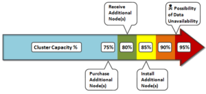
When deciding to add new nodes to an existing cluster or pool, contact your sales team to order the nodes well in advance of the cluster or pool running short on space. The recommendation is to start planning for additional capacity when the cluster or pool reaches 75% full. This will allow sufficient time to receive and install the new hardware, while still maintaining sufficient free space.

Here’s the recommended timeline for cluster capacity planning purposes:

If your data availability and protection SLA varies across different data categories (for example, home directories, file services, etc), ensure that any snapshot, replication and backup schedules are configured accordingly to meet the required availability and recovery objectives, and fit within the overall capacity plan.

Consider configuring a separate accounting quota for /ifs/home and /ifs/data directories (or wherever data and home directories are provisioned) to monitor aggregate disk space usage and issue administrative alerts as necessary to avoid running low on overall capacity.

DataIQ and InsightIQ both provide detailed monitoring and trending functionality to help with capacity consumption projections and usage forecasting.

For optimal performance in any size cluster, the recommendation is to maintain at least 10% free space in each pool of a cluster.

To better protect smaller clusters (containing 3 to 7 nodes) the recommendation is to maintain 15 to 20% free space. A full smartfail of a node in smaller clusters may require more than one node’s worth of space. Keeping 15 to 20% free space can allow the cluster to continue to operate while support assists with recovery plans.

Also, it pays to plan for contingencies: Having a fully updated backup of your data can limit the risk of data loss if a node fails.

Maintaining appropriate protection levels

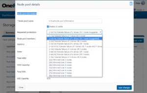
Ensure your cluster and pools are protected at the appropriate level. Every time you add nodes, re-evaluate protection levels. OneFS includes a ‘suggested protection’ function that calculates a recommended protection level based on cluster configuration, and alerts you if the cluster falls below this suggested level

OneFS supports several protection schemes. These include the ubiquitous +2d:1n, which protects against two drive failures or one node failure. Use the recommended protection level for a particular cluster configuration. This recommended level of protection is clearly marked as ‘suggested’ in the OneFS WebUI storage pools configuration pages, and is typically configured by default.

Monitoring cluster capacity

  • Configure alerts. Set up event notification rules so that you will be notified when the cluster begins to reach capacity thresholds. Make sure to enter a current email address in order to receive the notifications.
  • Monitor alerts. The cluster sends notifications when it has reached 95 percent and 99 percent capacity. On some larger clusters, 5 percent (or even 1 percent) capacity remaining might mean that a lot of space is still available, so you might be inclined to ignore these notifications. However, it is best to pay attention to the alerts, closely monitor the cluster, and have a plan in place to take action when necessary.
  • Monitor ingest rate. It’s important to understand the rate at which data is coming in to the cluster or pool. Options to do this include:
    • SNMP
    • SmartQuotas
    • FSAnalyze
    • DataIQ/InsightIQ
  • Use SmartQuotas to monitor and enforce administrator-defined storage limits. SmartQuotas manages storage use, monitors disk storage, and issues alerts when disk storage limits are exceeded. Although it does not provide the same detail of the file system that FSAnalyze does, SmartQuotas maintains a real-time view of space utilization so that you can quickly obtain the information you need.
  • Run FSAnalyze jobs. FSAnalyze is a job-engine job that the system runs to create data for file system analytics tools. FSAnalyze provides details about data properties and space usage within the /ifs directory. Unlike SmartQuotas, FSAnalyze updates its views only when the FSAnalyze job runs. Since FSAnalyze is a fairly low-priority job, it can sometimes be preempted by higher-priority jobs and therefore take a long time to gather all of the data.

Managing data

Regularly archive data that is rarely accessed and delete any unused and unwanted data. Ensure that pools do not become too full by setting up file pool policies to move data to other tiers and pools.

Provisioning additional capacity

To ensure that your cluster or pools do not run out of space, you can create more clusters, replace smaller-capacity nodes with larger-capacity nodes, or add new nodes to existing clusters or pools. If you decide to add new nodes to an existing cluster or pool, contact your sales representative to order the nodes long before the cluster or pool runs out of space. EMC recommends that you begin the ordering process when the cluster or pool reaches 80% used capacity. This will allow enough time to receive and install the new equipment and still maintain enough free space.

Managing snapshots

Sometimes a cluster has many old snapshots that consume significant capacity. Reasons for this include inefficient deletion schedules, degraded cluster preventing job execution, expired SnapshotIQ license, etc. Retaining only the snapshots required to support the data availability and protection SLAs will help guard against unintended capacity utilization.

Ensuring all nodes are supported and compatible

Each version of OneFS supports only certain nodes. Refer to the “OneFS and node compatibility” section of the PowerScale Supportability and Compatibility Guide for a list of which nodes are compatible with each version of OneFS. When upgrading OneFS, make sure that the new version supports your existing nodes. If it does not, you might need to replace the nodes.

Space and performance are optimized when all nodes in a pool are compatible. When new nodes are added to a cluster, OneFS automatically provisions nodes into pools with other nodes of compatible type, hard drive capacity, SSD capacity, and RAM. Occasionally, however, the system might put a node into an unexpected location. If you believe that a node has been placed into a pool incorrectly, contact Dell Technical Support for assistance. Different versions of OneFS have different rules regarding what makes nodes compatible

Enabling Virtual Hot Spare and Spillover

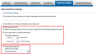
OneFS also provides a Virtual Hot Spare (VHS), who’s purpose is to keep space in reserve in case you need to smartfail drives when the cluster gets close to capacity. Enabling VHS will not give you more free space, but it will help protect your data in the event that space becomes scarce. VHS is enabled by default. It’s strongly recommended that you do not disable VHS unless directed by a Support engineer. If you disable VHS in order to free some space, the space you just freed will probably fill up again very quickly with new writes. At that point, if a drive were to fail, you might not have enough space to smartfail the drive and re-protect its data, potentially leading to data loss. If VHS is disabled and you upgrade OneFS, VHS will remain disabled. If VHS is disabled on your cluster, first check to make sure the cluster has enough free space to safely enable VHS, and then enable it.

Spillover allows data that is being sent to a full pool to be diverted to an alternate pool. Spillover is enabled by default on clusters that have more than one pool. If you have a SmartPools license on the cluster, you can disable Spillover. However, it is recommended that you keep Spillover enabled. If a pool is full and Spillover is disabled, you might get a “no space available” error but still have a large amount of space left on the cluster.

Run OneFS Healthchecks

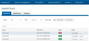
Regularly run and review the OneFS health checks. These can be easily configured and managed from either the WebUI or CLI:

Use OneFS Healthchecks to confirm there are no current cluster issues and that OneFS’ configuration is as expected.

OneFS Isi Set Command

In the previous article, we looked at the scope of the ‘isi get’ CLI command. To compliment this, OneFS also provides the ‘isi set’ utility, which allows configuration of OneFS-specific file attributes.

This command works similarly to the UNIX ‘chmod’ command, but on OneFS-centric attributes, such as protection, caching, encoding, etc. As with isi get, files can be specified by path or LIN in the isi set syntax.

The following table describes in more detail the various flags and options available for the isi set command:

Command Option Description
-f Suppresses warnings on failures to change a file.
-L Specifies file arguments by LIN instead of path.
-n Displays the list of files that would be changed without taking any action.
-v Displays each file as it is reached.
-r Performs a restripe on specified file.
-R Sets protection recursively on files.
-p <policy> Specifies protection policies in the following forms: +M Where M is the number of node failures that can be tolerated without loss of data.

+M must be a number from, where numbers 1 through 4 are valid.

+D:M Where D indicates the number of drive failures and M indicates number of node failures that can be tolerated without loss of data. D must be a number from 1 through 4 and M must be any value that divides into D evenly. For example, +2:2 and +4:2 are valid, but +1:2 and +3:2 are not.

Nx Where N is the number of independent mirrored copies of the data that will be stored. N must be a number, with 1 through 8 being valid choices.

-w <width> Specifies the number of nodes across which a file is striped. Typically, w = N + M, but width can also mean the total of the number of nodes that are used. You can set a maximum width policy of 32, but the actual protection is still subject to the limitations on N and M.
-c {on | off} Specifies whether write-caching (coalescing) is enabled.
-g <restripe goal> Used in conjunction with the -r flag, -g specifies the restripe goal. The following values are valid:

·         repair

·         reprotect

·         rebalance

·         retune

-e <encoding> Specifies the encoding of the filename.
-d <@r drives> Specifies the minimum number of drives that the file is spread across.
-a <value> Specifies the file access pattern optimization setting. Ie. default, streaming, random, custom, disabled.
-l <value> Specifies the file layout optimization setting. This is equivalent to setting both the -a and -d flags. Values are concurrency, streaming, or random
–diskpool <id | name> Sets the preferred diskpool for a file.
-A {on | off} Specifies whether file access and protections settings should be managed manually.
-P {on | off} Specifies whether the file inherits values from the applicable file pool policy.
-s <value> Sets the SSD strategy for a file. The following values are valid: If the value is metadata-write, all copies of the file’s metadata are laid out on SSD storage if possible, and user data still avoids SSDs. If the value is data, Both the file’s meta- data and user data (one copy if using mirrored protection, all blocks if FEC) are laid out on SSD storage if possible.

avoid Writes all associated file data and metadata to HDDs only. The data and metadata of the file are stored so that SSD storage is avoided, unless doing so would result in an out-of-space condition.

metadata Writes both file data and metadata to HDDs. One mirror of the metadata for the file is on SSD storage if possible, but the strategy for data is to avoid SSD storage.

metadata-write Writes file data to HDDs and metadata to SSDs, when available. All copies of metadata for the file are on SSD storage if possible, and the strategy for data is to avoid SSD storage.

data Uses SSD node pools for both data and metadata. Both the metadata for the file and user data, one copy if using mirrored protection and all blocks if FEC, are on SSD storage if possible.

<file> {<path> | <lin>} Specifies a file by path or LIN.

–nodepool <id | name> Sets the preferred nodepool for a file.
–packing {on | off} Enables storage efficient packing off a small file into a shadow store container.
–mm-[access | packing | protection] { on|off} The ‘manually manage’ prefix flag for the access, packing, and protection options described above. This ‘—mm’ flag controls whether the SmartPools job will act on the specified file or not. On means SmartPools will ignore the file, and vice versa.

Here are some examples of the isi set command in action.

For example, the following syntax will recursively configure a protection policy of +2d:1n on /ifs/data/testdir1 and its contents:

# isi set –R -p +2:1 /ifs/data/testdir1

To enable write caching coalescer on testdir1 and its contents, run:

# isi set –R -c on /ifs/data/testdir1

With the addition of the –n flag, no changes will actually be made. Instead, the list of files and directories that would have write enabled is returned:

# isi set –R –n -c on /ifs/data/testdir2

The following command will configure ISO-8859-1 filename encoding on testdir3 and contents:

# isi set –R –e ISO-8859-1 /ifs/data/testdir3

To configure streaming layout on the file ‘test1’, run:

# isi set -l streaming test1

The following syntax will set a metadata-write SSD strategy on testdir1 and its contents:

# isi set –R -s metadata-write /ifs/data/testdir1

To performs a file restripe operation on the file2:

# isi set –r file2

To configure write caching on file3 via its LIN address, rather than file name:

# isi set –c on –L ` # isi get -DD file1 | grep -i LIN: | awk {‘print $3}’` 1:0054:00f6

After setting streaming access, isi get reports that streaming prefetch is enabled:

# isi get file2.tst default   6+2/2 concurrency on    file2.tst # isi set -a streaming file2.tst # isi get file2.tst POLICY    LEVEL PERFORMANCE COAL  FILE default   6+2/2 streaming   on    file2.tst

For streaming layout, the ‘@’ suffix notation indicates how many drives the file is written over. Streaming layout  optimizes for a larger number of spindles than concurrency or random.

# isi get file2.tst POLICY    LEVEL PERFORMANCE COAL  FILE default   6+2/2 concurrency on    file2.tst # isi set -l streaming file2.tst # isi get file2.tst POLICY    LEVEL PERFORMANCE COAL  FILE default   6+2/2 streaming/@18 on    file2.tst

The number of drives to spread file across can also be specified with ‘isi get –d’. For example:

# isi set -d 6 file2.tst # isi get file2.tst POLICY    LEVEL PERFORMANCE COAL  FILE default   6+2/2 streaming/@6 on    file2.tst

So there you have it – several examples demonstrating the power of the OneFS ‘isi set’ command, in combination with its ‘isi get’ counterpart.


OneFS Isi Get Command

One of the lesser publicized but highly versatile tools in OneFS is the ‘isi get’ command line utility. It can often prove invaluable for generating a vast array of useful information about OneFS filesystem objects. In its most basic form, the command outputs this following information:

  • Protection policy
  • Protection level
  • Layout strategy
  • Write caching strategy
  • File name

For example:

# isi get /ifs/data/file2.txt POLICY              LEVEL     PERFORMANCE      COAL      FILE default             4+2/2     concurrency      on        file2.txt

Here’s what each of these categories represents:

POLICY:  Indicates the requested protection for the object, in this case a text file. This policy field is displayed in one of three colors:

Requested Protection Policy Description
Green Fully protected
Yellow Degraded protection under a mirroring policy
Red Under-protection using FEC parity protection

LEVEL:  Displays the current actual on-disk protection of the object. This can be either FEC parity protection or mirroring. For example:

Protection  Level Description
+1n Tolerate failure of 1 drive OR 1 node (Not Recommended)
+2d:1n Tolerate failure of 2 drives OR 1 node
+2n Tolerate failure of 2 drives OR 2 nodes
+3d:1n Tolerate failure of 3 drives OR 1 node
+3d:1n1d Tolerate failure of 3 drives OR 1 node AND 1 drive
+3n Tolerate failure of 3 drives or 3 nodes
+4d:1n Tolerate failure of 4 drives or 1 node
+4d:2n Tolerate failure of 4 drives or 2 nodes
+4n Tolerate failure of 4 nodes
2x to 8x Mirrored over 2 to 8 nodes, depending on configuration

PERFORMANCE:  Indicates the on-disk layout strategy, for example:

Data Access Setting Description On Disk Layout Caching
Concurrency Optimizes for current load on cluster, featuring many simultaneous clients. Recommended for mixed workloads. Stripes data across the minimum number of drives required to achieve the configured data protection level. Moderate prefetching
Streaming Optimizes for streaming of a single file. For example, fast reading by a single client. Stripes data across a larger number of drives. Aggressive prefetching
Random Optimizes for unpredictable access to a file. Performs almost no cache prefetching. Stripes data across the minimum number of drives required to achieve the configured data protection level. Little to no prefetching

COAL:  Indicates whether the Coalescer, OneFS’s NVRAM based write cache, is enabled. The coalescer provides failure-safe buffering to ensure that writes are efficient and read-modify-write operations avoided.

The isi get command also provides a number of additional options to generate more detailed information output. As such, the basic command syntax for isi get is as follows:

isi get {{[-a] [-d] [-g] [-s] [{-D | -DD | -DDC}] [-R] <path>}  | {[-g] [-s] [{-D | -DD | -DDC}] [-R] -L <lin>}}

Here’s the description for the various flags and options available for the command:

Command Option Description
-a Displays the hidden “.” and “..” entries of each directory.
-d Displays the attributes of a directory instead of the contents.
-g Displays detailed information, including snapshot governance lists.
-s Displays the protection status using words instead of colors.
-D Displays more detailed information.
-DD Includes information about protection groups and security descriptor owners and groups.


-DDC Includes cyclic redundancy check (CRC) information.
-L <LIN> Displays information about the specified file or directory. Specify as a file or directory LIN.
-O Displays the logical overlay information and compressed block count when viewing a compressed file’s details.
-R Displays information about the subdirectories and files of the specified directories.

The following command shows the detailed properties of a directory, /ifs/data. Note that the output has been truncated slightly to aid readability:

# isi get -D data  POLICY   W   LEVEL PERFORMANCE COAL  ENCODING      FILE              IADDRS default       4x/2 concurrency on    N/A           ./                <1,36,268734976:512>, <1,37,67406848:512>, <2,37,269256704:512>, <3,37,336369152:512> ct: 1459203780 rt: 0  ************************************************* * IFS inode: [ 1,36,268734976:512, 1,37,67406848:512, 2,37,269256704:512, 3,37,336369152:512 ]     ************************************************* *  Inode Version:      6 *  Dir Version:        2 *  Inode Revision:     6 *  Inode Mirror Count: 4 *  Recovered Flag:     0 *  Restripe State:     0 *  Link Count:         3 *  Size:               54 *  Mode:               040777 *  Flags:              0xe0 *  Stubbed:            False *  Physical Blocks:    0 *  LIN:                1:0000:0004    *  Logical Size:       None *  Shadow refs:        0 *  Do not dedupe:      0 *  Last Modified:      1461091982.785802190 *  Last Inode Change:  1461091982.785802190 *  Create Time:        1459203780.720209076 *  Rename Time:        0 *  Write Caching:      Enabled  *  Parent Lin          2 *  Parent Hash:        763857 *  Snapshot IDs:       None *  Last Paint ID:      47 *  Domain IDs:         None *  LIN needs repair:   False *  Manually Manage: *       Access         False *       Protection     True *  Protection Policy:  default *  Target Protection:  4x *  Disk pools:         policy any pool group ID -> data target  z x410_136tb_1.6tb-ssd_256gb:32(32), metadata target x410_136tb_1.6tb-ssd_256gb:32(32) *  SSD Strategy:       metadata-write  { *  SSD Status:         complete *  Layout drive count: 0 *  Access pattern: 0 *  Data Width Device List: *  Meta Width Device List: * *  File Data (78 bytes): *    Metatree Depth: 1 *  Dynamic Attributes (40 bytes):         ATTRIBUTE                OFFSET SIZE         New file attribute       0      23         Isilon flags v2          23     3         Disk pool policy ID      26     5         Last snapshot paint time 31     9 ************************************************* *  NEW FILE ATTRIBUTES | *  Access attributes:  active *  Write Cache:  on *  Access Pattern:  concurrency *  At_r: 0 *  Protection attributes:  active *  Protection Policy:  default

* Disk pools:         policy any pool group ID

*  SSD Strategy:       metadata-write * *************************************************

Here is what some of these lines indicate:

  1. OneFS command to display the file system properties of a directory or file.
  2. The directory’s data access pattern is set to concurrency
  3. Write caching (Coalescer) is turned on.
  4. Inode on-disk locations.
  5. Primary LIN.
  6. Indicates the disk pools that the data and metadata are targeted to.
  7. The SSD strategy is set to metadata-write.
  8. Files that are added to the directory are governed by these settings, most of which can be changed by applying a file pool policy to the directory.

From the WebUI, a subset of the ‘isi get –D’ output is also available from the OneFS File Explorer. This can be accessed by browsing to File System > File System Explorer and clicking on ‘View Property Details’ for the file system object of interest.

One question that is frequently asked is how to find where a file’s inodes live on the cluster. The ‘isi get -D’ command output makes this fairly straightforward to answer. Take the file /ifs/data/file1, for example:

# isi get -D /ifs/data/file1 | grep -i "IFS inode" * IFS inode: [ 1,9,8388971520:512, 2,9,2934243840:512, 3,8,9568206336:512 ]

This shows the three inode locations for the file in the *,*,*:512 notation. Let’s take the first of these:

1,9,8388971520:512

From this, we can deduce the following:

  • The inode is on node 1, drive 9 (logical drive number).
  • The logical inode number is 8388971520.
  • It’s an inode block that’s 512 bytes in size (Note: OneFS data blocks are 8kB in size).

Another example of where isi get can be useful is in mapping between a file system object’s pathname and its LIN (logical inode number). This might be for translating a LIN returned by an audit logfile or job engine report into a valid filename, or finding an open file from vnodes output, etc.

For example, say you wish to know which configuration file is being used by the cluster’s DNS service:

First, inspect the busy_vnodes output and filter for DNS:

# sysctl efs.bam.busy_vnodes | grep -i dns vnode 0xfffff8031f28baa0 (lin 1:0066:0007) is fd 19 of pid 4812: isi_dnsiq_d

This, amongst other things, provides the LIN for the isi_dnsiq_d process. The output can be further refined to just the LIN address as such:

# sysctl efs.bam.busy_vnodes | grep -i dns | awk '{print $4}' | sed -E 's/\)//' 1:0066:0007

This LIN address can then be fed into ‘isi get’ using the ‘-L’ flag, and a valid name and path for the file will be output:

# isi get -L `sysctl efs.bam.busy_vnodes | grep -i dns | grep -v "(lin 0)" | awk '{print $4}' | sed -E 's/\)//'` A valid path for LIN 0x100660007 is /ifs/.ifsvar/modules/flexnet/flx_config.xml

This confirms that the XML configuration file in use by isi_dnsiq_d is flx_config.xml.

OneFS 8.2.1 and later also sees the addition of a ‘-O’ logical overlay flag to ‘isi get’ CLI utility for viewing a file’s compression details. For example:

# isi get –DDO file1 * Size:           167772160 * PhysicalBlocks: 10314 * LogicalSize:    167772160 PROTECTION GROUPS lbn0: 6+2/2 2,11,589365248:8192[COMPRESSED]#6 0,0,0:8192[COMPRESSED]#10 2,4,691601408:8192[COMPRESSED]#6 0,0,0:8192[COMPRESSED]#10 Metatree logical blocks: zero=32 shadow=0 ditto=0 prealloc=0 block=0 compressed=64000

The logical overlay information is described under the ‘protection groups’ output. This example shows a compressed file where the sixteen-block chunk is compressed down to six physical blocks (#6) and ten sparse blocks (#10). Under the ‘Metatree logical blocks’ section, a breakdown of the block types and their respective quantities in the file is displayed – including a count of compressed blocks.

When compression has occurred, the ‘df’ CLI command will report a reduction in used disk space and an increase in available space. The ‘du’ CLI command will also report less disk space used.

A file that for whatever reason cannot be compressed will be reported as such:

4,6,900382720:8192[INCOMPRESSIBLE]#1

So, to recap, the ‘isi get’ command provides a whole heap of useful information about an individual, or set of, file system objects.

OneFS Endurant Cache

The Endurant Cache, or EC, is OneFS’ caching mechanism for synchronous writes – or writes that require a stable write acknowledgement to be returned to an NFS client.

The EC operates in conjunction with the OneFS write cache, or coalescer, to ingest, protect and aggregate small, synchronous NFS writes. The incoming write blocks are staged to NVRAM, ensuring the integrity of the write, even during the unlikely event of a node’s power loss.  Furthermore, EC also creates multiple mirrored copies of the data, further guaranteeing protection from single node and, if desired, multiple node failures.

EC improves the latency associated with synchronous writes by reducing the time to acknowledgement back to the client. This process removes the Read-Modify-Write (R-M-W) operations from the acknowledgement latency path, while also leveraging the coalescer to optimize writes to disk. The EC is also tightly coupled with OneFS’ multi-threaded I/O (Multi-writer) process, to support concurrent writes from multiple client writer threads to the same file. And the design of EC ensures that the cached writes do not impact snapshot performance.

The Endurant Cache uses write logging to combine and protect small writes at random offsets into 8K linear writes. To achieve this, the writes go to a mirrored files, or Logstores. The response to a stable write request can be sent once the data is committed to the Logstore. Logstores can be written to by several threads from the same node, and are highly optimized to enable low-latency concurrent writes.

Note that if a write uses the EC, the coalescer must also be used. If the coalescer is disabled on a file, but the EC is enabled, the coalescer will still be active, with all data backed by the EC.

Imagine an NFS client that wishes to write a file to a PowerScale cluster over NFS with the O_SYNC flag set, requiring a confirmed or synchronous write acknowledgement. The following sequence of events will occur to facilitate a stable write.

  1. The client, connected to node 2, begins the write process sending protocol level blocks. 4K is the optimal block size for the Endurant Cache.

  1. The NFS client’s writes are temporarily stored in the write coalescer portion of node 2’s RAM. The Write Coalescer aggregates uncommitted blocks so that the OneFS can, ideally, write out full protection groups where possible, reducing latency over protocols that allow “unstable” writes. Writing to RAM has far less latency that writing directly to disk.
  2. Once in the write coalescer, the Endurant Cache log-writer process writes mirrored copies of the data blocks in parallel to the EC Log Files.

The protection level of the mirrored EC log files is the same as that of the data being written by the NFS client.

  1. Once the data copies are received into the EC Log Files, a stable write exists and a write acknowledgement (ACK) is returned to the NFS client confirming the stable write has occurred. The client assumes the write is completed and can close the write session.

  1. The Write Coalescer then processes the file just like a non-EC write at this point. The Write Coalescer fills and is routinely flushed as required as an asynchronous write via to the Block Allocation Manager (BAM) and the BAM Safe Write (BSW) path processes.
  2. The file is split into 128K Data Stripe Units (DSUs), parity protection (FEC) is calculated and FEC Stripe Units (FSUs) are created.

  1. The layout and write plan is then determined, and the stripe units are written to their corresponding nodes’ L2 Cache and NVRAM. The EC logfiles are cleared from NVRAM at this point. OneFS uses a Fast Invalid Path process to de-allocate the EC Log Files from NVRAM.

  1. Stripe Units are then flushed to physical disk.
  2. Once written to physical disk, the Data Stripe Unit (DSU) and FEC Stripe Unit (FSU) copies created during the write are cleared from NVRAM but remain in L2 cache until flushed to make room for more recently accessed data.

The number of logfile mirrors that are created by EC is always one more than the on-disk protection level of the file. For example:

File Protection Level # EC Mirrored Copies
+1n 2
2x 3
+2d:1n 3
+2n 3
+3d:1n1d 4
+3n 4
+4n 5

The EC mirrors are only used if the initiator node is lost. In the unlikely event that this occurs, the participant nodes replay their EC journals and complete the writes.

If the write is an EC candidate, the data remains in the coalescer, an EC write is constructed, and the appropriate coalescer region is marked as EC. The EC write is a write into a logstore (hidden mirrored file) and the data is placed into the journal.

Assuming the journal is sufficiently empty, the write is held there (cached) and only flushed to disk when the journal is full, thereby saving additional disk activity.

An optimal workload for EC involves small-block synchronous, sequential writes – something like an audit or redo log, for example. In that case, the coalescer will accumulate a full protection group’s worth of data and be able to perform an efficient FEC write.

The happy medium is a small-block sync (vmdk) type load where the I/O rate is low, and the client is latency-sensitive. In this case, the latency will be reduced and, if the I/O rate is low enough, it won’t create serious pressure.

The undesirable scenario is when the cluster is already spindle-bound and the workload is such that it generates a lot of journal pressure. In this case, EC is just going to aggravate things.

Although on by default, setting the boolean sysctl efs.bam.ec.mode value to ‘1’ will enable the Endurant Cache:

# isi_for_array –s isi_sysctl_cluster efs.bam.ec.mode=1

EC can also be enabled & disabled per directory:

# isi set -c [on|off|endurant_all|coal_only] <directory_name>

To enable the coalescer but switch of EC, run:

# isi set -c coal_only

And to disable the Endurant Cache completely:

# isi_for_array –s isi_sysctl_cluster efs.bam.ec.mode=0

A return value of zero on each node from the following command will verify that EC is disabled across the cluster:

# isi_for_array –s sysctl efs.bam.ec.stats.write_blocks efs.bam.ec.stats.write_blocks: 0

If the output to this command is incrementing, EC is delivering stable writes.

As mentioned previously, EC applies to stable writes, namely:

  • Writes with O_SYNC and/or O_DIRECT flags set
  • Files on synchronous NFS mounts

When it comes to analyzing any performance issues involving EC workloads, consider the following:

  • What changed with the workload?
  • If upgrading OneFS, did the prior version also have EC enable?
  • If the workload has moved to new cluster hardware:
  • Was there a large change in spindle or node count?
  • Has the OneFS protection level changed?
  • Is the SSD strategy the same?
  • Does the performance issue occur during periods of high CPU utilization?
  • Which part of the workload is creating a deluge of stable writes?

Disabling EC is typically done cluster-wide and this can adversely impact certain workflow elements. If the EC load is localized to a subset of the files being written, an alternative way to reduce the EC heat might be to disable the coalescer buffers for some particular target directories, which would be a more targeted adjustment. This can be configured via the isi set –c off command.

One of the more likely causes of performance degradation is from applications aggressively flushing over-writes and, as a result, generating a flurry of ‘commit’ operations. This can generate heavy read/modify/write (r-m-w) cycles, inflating the average disk queue depth, and resulting in significantly slower random reads. The isi statistics protocol CLI command output will indicate whether the ‘commit’ rate is high.

Bear in mind that synchronous writes do not require using the NFS ‘sync’ mount option! Any programmer who is concerned with write persistence can simply specify an O_FSYNC or O_DIRECT flag on the open() operation to force synchronous write semantics for that fie handle. With Linux, writes using O_DIRECT will be separately accounted-for in the Linux ‘mountstats’ output.

Note: Although almost exclusively associated with NFS, the EC code is actually protocol-agnostic. If writes are synchronous (write-through) and are either misaligned or smaller than 8k, they have the potential to trigger EC, regardless of the protocol.

The Endurant Cache can often provide a significant latency benefit for small (eg. 4K), random synchronous writes – albeit at a cost of some additional work for the system.

However, it’s worth bearing the following in mind:

  • EC is not intended for more general purpose I/O.
  • There is a finite amount of EC available. As load increases, EC can potentially ‘fall behind’ and end up being a bottleneck.
  • Endurant Cache does not improve read performance, since it’s strictly part of the write process.
  • EC will not increase performance of asynchronous writes – only synchronous writes.

OneFS TreeDelete

There have been several recent enquires about large scale file deletes, so a quick article on this topic seemed appropriate.

For example, imagine a workflow that involves creating and deleting thousands or millions of files of varying sizes each day. The serial deletion of these files at the NFS and SMB host level would be incredibly slow and inefficient. Fortunately, OneFS has a purpose-built tool for this: the TreeDelete job.

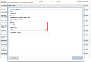
Within the OneFS Job Engine, TreeDelete is a single phase job which runs by default with ‘medium’ impact and a default priority value of 4.

The command line syntax to kick off an instance of this job is:

# isi job jobs start treedelete –-paths <path>

Or, alternatively, via the platform API:

# curl -k -u username:password -H 'Content-Type: application/json' --request POST --data '{"paths": ["<path>"], "type": "treedelete", "allow_dup": true}' 'https://<cluster_IP>:8080/platform/1/job/jobs'

Note that the ‘path’ argument for these commands must be within the cluster’s /ifs partition. TreeDelete will not work on any of the other OneFS filesystem partitions, such as /root, /var, etc, which will fail with “non-valid partition” error. Also, if attempting to delete /ifs/.ifsvar, the TreeDelete job will fail with “Invalid path specified”. Beyond these however, TreeDelete does not prompt to ensure that you’ve selected the desired directory path to remove, etc. So, to avoid any unpleasant surprises, check twice before running the TreeDelete job to ensure that you have configured the job correctly and specified the correct path(s):  There is no ‘undo’ button.

Multiple directory paths can be specified as part of this command. For example:

# isi job jobs start treedelete --paths /ifs/dir1  --paths /ifs/dir2 --paths /ifs/dir3 –paths /ifs/dir4

Deleting more than 60 paths in a single TreeDelete job command has been successful. And you’ll likely hit the command line max length well before finding a tree delete path limit. Additionally, you can always queue up to thirty TreeDelete jobs, if desired.

TreeDelete job progress is reported a percentage in “isi stat” output:

 TreeDelete (12)            MEDIUM     02/16 11:34  00:01:11    24%  /ifs/data/recycle

Upon completion, the job status will be reported as such:

Fri Mar 5 23:19:26 2021 Daemon[57225]: TreeDelete job deleted 131028 files/dirs, 322GB, with 0 errors

Plus, a full job report, containing deleted data counts and capacities, cluster resource utilization, and job engine stats, etc, is available as follows:

# isi job reports view 12 -v

TreeDelete[12] phase 1 (2021-03-05T23:19:26)

--------------------------------------------

Paths                                     [ "/ifs/data/trash" ]

Files                                     131028

Directories                               101

Apparent size                             267387005115

Physical size                             357773443072

JE/Coordinator/Merge microseconds         { sum = 55, mean = 11, stdev = 8.12404 }

JE/Error Count                            0

JE/Group at phase end                     [ "<1,8> :{ 1-4:0-14, smb: 1-4, nfs: 1-4, swift: 1-4, all_enabled_protocols: 1-4, isi_cbind_d: 1-4, lsass: 1-4, s3: 1-4 }" ]

JE/Manager/Merge microseconds             { sum = 150, mean = 5.17241, stdev = 2.76766 }

JE/Stats/CPU avg                          13.73%

JE/Stats/CPU max                          506.84%

JE/Stats/CPU max node                     1

JE/Stats/CPU min                          0.00%

JE/Stats/CPU min node                     2

JE/Stats/IO/Current job/Read bytes        0 bytes

JE/Stats/IO/Current job/Reads             0

JE/Stats/IO/Current job/Write bytes       741941248 bytes (707.57M)

JE/Stats/IO/Current job/Writes            90569

JE/Stats/IO/Non-JE/Read bytes             0 bytes

JE/Stats/IO/Non-JE/Reads                  0

JE/Stats/IO/Non-JE/Write bytes            26492928 bytes (25.27M)

JE/Stats/IO/Non-JE/Writes                 3234

JE/Stats/IO/Other jobs/Read bytes         0 bytes

JE/Stats/IO/Other jobs/Reads              0

JE/Stats/IO/Other jobs/Write bytes        36274176 bytes (34.59M)

JE/Stats/IO/Other jobs/Writes             4428

JE/Stats/Memory/RSS size avg              43867136 bytes (41.83M)

JE/Stats/Memory/RSS size max              46411776 bytes (44.26M)

JE/Stats/Memory/RSS size max node         4

JE/Stats/Memory/RSS size min              42795008 bytes (40.81M)

JE/Stats/Memory/RSS size min node         3

JE/Stats/Memory/VM size avg               91016338 bytes (86.80M)

JE/Stats/Memory/VM size max               93835264 bytes (89.49M)

JE/Stats/Memory/VM size max node          1

JE/Stats/Memory/VM size min               90251264 bytes (86.07M)

JE/Stats/Memory/VM size min node          3

JE/Time elapsed                           35 seconds

JE/Time working                           35 seconds

JE/Worker/Finalize item microseconds      { sum = 0, mean = 0, stdev = -- }

JE/Worker/Finalize task microseconds      { sum = 20, mean = 0.689655, stdev = 1.93165 }

JE/Worker/Next item microseconds          { sum = 103567, mean = 20.1846, stdev = 113.937 }

JE/Worker/Process item microseconds       { sum = 34027935, mean = 6644.78, stdev = 4183.41 }

JE/Worker/Process item total microseconds { sum = 34027935, mean = 6644.78, stdev = 4183.41 }


TreeDelete[12] Job Summary

--------------------------

Final Job State  Succeeded

Phase Executed

TreeDelete requires OneFS to perform a treewalk within the filesystem namespace as the first task, in order to determine how much work it will need to perform.  For instance, a TreeDelete job starting at /ifs/temp will traverse the directory hierarchy down to the lowest-level subdirectories.  For more complex TreeDelete configurations, the job will traverse all the configured policy paths, so it’s fair to say that TreeDelete can be a relatively metadata-heavy process.

As such, enabling metadata write acceleration (all metadata housed on SSDs) has the potential to speed up TreeDelete substantially. However, for optimal speed here, there are other considerations.

Layout can gain you a lot, provided you’re also smart about running multiple threads to do the deletions. If you have lots of smaller directories, delete performance is likely to be very good. If you have a few wide directories, it’s not likely to help much.

Be aware that, even though TreeDelete is multithreaded, if the deletion happens in a directory, it still requires an exclusive lock on the directory. This would slow the deletion down as the job’s worker thread will have to wait on getting a lock to do the deletion. So, if you have the available I/O, you can literally delete files stored in ten separate directory ten times as quickly deleting the same files from a single directory.

So ‘manually’ spreading the delete load has the potential to be faster. Also, deleting large files is quite expensive in terms of free-space management. For files larger than a tunable threshold in size, each node will, by default, spin up a background thread to delete the file.

A general rule is:

More directories = more TreeDelete parallelism = better performance.

Running the TreeDelete job at high impact, rather than the default medium, will increase the number of threads. However, this is only recommended for an idle cluster – not if there is other work happening.

Another option for data housekeeping on a cluster is using TreeDelete to maintain a common ‘recycle bin’. This can be done by create a directory like /ifs/recycle for users to dump their unwanted files in, via Windows file explorer, or the UNIX/linux ‘mv’ command, etc.  Then periodically manually run or set up a cron job for the treedelete job. For example:

# isi job jobs start treedelete --path /ifs/recycle --priority 10 --policy low

Note that the TreeDelete job will also delete the /ifs/recycle folder. If this is a problem, you can also:

  • Set an advisory quota on the parent directory, which will prevent it from being deleted. However, this requires SmartQuotas to be licensed on the cluster.
  • Add a cron job to recreate the recycle directory after the TreeDelete has completed.
  • Use a symlink for the current recycle directory. When you want to empty it, switch the symlink to a new empty directory, then start the job to delete the old directory.
  • Add subdirectories to the parent directory and just delete the ‘junk’ subdirectory. Ie. /ifs/recycle/junk1, /ifs/recycle/junk2, /ifs/recycle/junk3. This will potentially have the added benefit of more directory parallelism, and potentially better performance.

Be aware of the potential for file name collisions in the recycle bin. If two users both attempt to move files with the same name the recycle bin, the second one will require delete permissions to the first one.

In order to immediately reclaim the deleted file space from a TreeDelete job run, it may be necessary to remove all snapshot policies in that project path, delete those snapshots, then move the project into the recycle bin and let TreeDelete take over. Even the moving data to the recycle bin tree can force SnapshotIQ to preserve blocks if the snap existed before prior to the data being moved.  To delete a project entirely, you must remove all snaps associated with that tree to actually get all of your space back.  This can potentially include snapshots taken higher in the tree. Be aware that some other jobs, such as the FilesystemAnalyze, ChangelistCreate, etc, can keep a snapshot at the /ifs level sitting around to make incremental FSA jobs run faster.

As mentioned above, be aware that TreeDelete will not, by default, delete a directory that is the root directory of a quota. However, TreeDelete in OneFS 8.2 and later contains a flag to remove the top level quota, if one exists, so the final rmdir does not fail. For example:

# isi job jobs start treedelete –delete-quotas --path /ifs/recycle

It’s also fairly straightforward to write simple scripts to run TreeDelete. For example, the following shell command looks for subdirectories one level under the parent path, ‘/ifs/recycle’, and instructs TreeDelete to remove them:

# for i in `find /ifs/recycle -type d –depth 1`; do isi job jobs start treedelete --path $i; done

Another approach can be used in situations (ie. Windows environments) where the directory names can contain whitespace:

# find /ifs/recycle -type d –depth 1 -print0 | xargs -0 -I % isi job jobs start treedelete --path “%”

This command will also combine each line of the file into a single line and pass to the path argument.

Note that if you have more than 30 directories, the command will likely fail because the job engine  cannot queue more than thirty jobs. However, when emptying out recycle bin(s), if you create a time-stamped sub-directory and move everything for deletion into it, and then TreeDelete this directory, the 30-job limit is avoided.

This is a common challenge across a range of verticals, and particular in the EDA realm, where there are a couple of creative solutions. In addition to custom tools, solution also include discovering the files via find and moving them to a /ifs/data/recycle/date/batch-number/…100,000 files. Treedelete can then be run on a schedule, one at a time per batch number, with low impact and off hours so as not to impact key work flow times.

For example, a TREEDELETE_OFF_HOURS job impact policy can be created, which might include ‘SAT 00:00 to Sun 00:00 AND MON 00:00 to 06:00 LOW’. The default impact of the job could then be reconfigured from MEDIUM to TREEDLETE_OFF_HOURS. This would mean that any time that a TreeDelete job is run without specifying ‘-o medium’, it would automatically inherit and execute the TREEDELETE_OFF_HOURS schedule.

When moving directories to a recycle bin, beware of not crossing quota domains. The performance impact will be significant since the quota traverse will require a copy, delete, and then the subsequent TreeDelete.

So there you have it – a couple of examples in which the TreeDelete job can simplify and improve the wall clock time for data removal.

Snapdiff with Changelist

Snapdiff with changelist has been introduced in OneFS 8.2.2.0. It can return what regions of a file have been changed. However this functionality is hidden from WebUI and CLI and I see many customers are very interested in this new feature. This article will walk you through an example.

To create a snapdiff changelist, you have to add the option “–create-diffs” which is disabled by default.

# isi job start changelistcreate --newer-snapid=24 --older-snapid=22 --create-diffs

Note, you will not see this option in the help or description page of the CLI command.

After that you can either use isi_changelist_mod command to view the outcome. To include snapdiff deltas in the output, you have to add the option “–x”

# isi_changelist_mod -a 22_24 --x
st_ino=4306829722 st_mode=0100700 st_size=2837 st_atime=1614240223 st_mtime=1614240223 st_ctime=1614240223 st_flags=285212896 cl_flags=ENTRY_MODIFIED path=/ifs/test/test.txt
offset:0 size:2837 type: data

You can also leverage PAPI for the same purpose. The corresponding PAPI endpoint is:

platform/10/snapshot/changelists/<CHANGELIST>/diff-regions/<LIN>

Note, it’s only available starting from platform/10. To get a very detailed description of the PAPI you can use the following URL:

platform/10/snapshot/changelists/<CHANGELIST>/diff-regions/<LIN>/?describe
Resource URL: /platform/10/snapshot/changelists/<CHANGELIST>/diff-regions/<LIN>

    Overview: This resource represents the collection of snap diff regions.

     Methods: GET

********************************************************************************

Method GET: Get snap diff regions of a file.

URL: GET /platform/10/snapshot/changelists/<CHANGELIST>/diff-regions/<LIN>

Query arguments:
 resume=<string> Continue returning results from previous call using this token
                 (token should come from the previous call, resume cannot be
                 used with other options).
 limit=<integer> Return no more than this many results at once (see resume).
offset=<integer> 

GET response body schema:
{
  "type": [
    {
      "additionalProperties": false, 
      "type": "object", 
      "description": "A list of errors that may be returned.", 
      "properties": {
        "errors": {
          "minItems": 1, 
          "items": {
            "additionalProperties": false, 
            "type": "object", 
            "description": "An object describing a single error.", 
            "properties": {
              "field": {
                "minLength": 1, 
                "type": "string", 
                "description": "The field with the error if applicable.", 
                "maxLength": 8192
              }, 
              "message": {
                "minLength": 1, 
                "type": "string", 
                "description": "The error message.", 
                "maxLength": 8192
              }, 
              "code": {
                "minLength": 1, 
                "type": "string", 
                "description": "The error code.", 
                "maxLength": 8192
              }
            }
          }, 
          "type": "array", 
          "maxItems": 65535
        }
      }
    }, 
    {
      "additionalProperties": false, 
      "type": "object", 
      "properties": {
        "diff_regions": {
          "minItems": 0, 
          "items": {
            "type": "object", 
            "properties": {
              "byte_count": {
                "required": true, 
                "minimum": 0, 
                "type": "integer", 
                "description": "Byte count of change region.", 
                "maximum": 18446744073709551615
              }, 
              "region_type": {
                "required": true, 
                "description": "Type of change region.", 
                "minLength": 4, 
                "enum": [
                  "sparse", 
                  "data", 
                  "unchanged"
                ], 
                "maxLength": 9, 
                "type": "string"
              }, 
              "start_offset": {
                "required": true, 
                "minimum": 0, 
                "type": "integer", 
                "description": "Starting byte offset of change region.", 
                "maximum": 18446744073709551615
              }
            }
          }, 
          "type": "array", 
          "maxItems": 18446744073709551615
        }, 
        "resume": {
          "minLength": 0, 
          "type": [
            "string", 
            "null"
          ], 
          "description": "Provide this token as the 'resume' query argument to continue listing results.", 
          "maxLength": 8192
        }
      }
    }
  ]
}

Here is the output for the same example:

URL:

https://192.168.116.188:8080/platform/10/snapshot/changelists/22_24/diff-regions/4306829722

Outcome:

{
"diff_regions" : 
[

{
"byte_count" : 2837,
"region_type" : "data",
"start_offset" : 0
}
],
"resume" : null
}


PowerScale OneFS SNMP Trap List

Hundreds of requests have been raised regarding the demand of OneFS SNMP Trap list for various releases and how it’s mapping to the CELOG events. Here are the links for the SNMP trap list (csv format) for each releases:

SNMP_Trap_List_8.0.0.0

SNMP_Trap_List_8.0.0.1

SNMP_Trap_List_8.0.0.2

SNMP_Trap_List_8.0.0.3

SNMP_Trap_List_8.0.0.4

SNMP_Trap_List_8.0.0.5

SNMP_Trap_List_8.0.0.6

SNMP_Trap_List_8.0.0.7

SNMP_Trap_List_8.0.1.0

SNMP_Trap_List_8.0.1.1

SNMP_Trap_List_8.0.1.2

SNMP_Trap_List_8.1.0.0

SNMP_Trap_List_8.1.0.1

SNMP_Trap_List_8.1.0.2

SNMP_Trap_List_8.1.0.3

SNMP_Trap_List_8.1.0.4

SNMP_Trap_List_8.1.1.0

SNMP_Trap_List_8.1.1.1

SNMP_Trap_List_8.1.2.0

SNMP_Trap_List_8.1.3.0

SNMP_Trap_List_8.2.0

SNMP_Trap_List_8.2.1

SNMP_Trap_List_8.2.2

SNMP_Trap_List_9.0.0.0

SNMP_Trap_List_9.1.0.0


Creating OneFS Changelists

In the previous article, we examined the context around OneFS changelists and the ChangelistCreate job. Next, let’s step through an example of creating and managing a simple changelist via the OneFS CLI.

Here’s a basic procedure:

  1. First, create a directory (ifs/data/test1) and add couple of files:
# mkdir -p -v /ifs/data/test1

# echo f1 > /ifs/data/test1/f1

# echo f2 > /ifs/data/test1/f2
  1. Next, take a snapshot of the directory:
# isi snap snaps create /ifs/data/test1
  1. Modify the data (edit f1, remove f2, add f3):
# echo f1 >> /ifs/data/test1/f1

# rm /ifs/data/test1/f2

# echo f3 > /ifs/data/test1/f3
  1. Take a second snapshot:
# isi snap snaps create /ifs/data/test1
  1. View the snapshot ID’s:
# isi snap snaps ls

ID   Name  Path        

------------------------

3    s3    /ifs/data/test1

5    s5    /ifs/data/test1

------------------------

Total: 2
  1. Start a ChangelistCreate job using the two snapshot IDs above, and allow it to run to completion. Once the job no longer appears in the ‘isi job jobs ls’ command output, you know it’s done:
# isi job jobs start ChangelistCreate --older-snapid 3 --newer-snapid 5

Started job [3]

# isi job jobs ls

ID   Type             State   Impact  Pri  Phase  Running Time

---------------------------------------------------------------

3    ChangelistCreate Running Low     5    2/4    9s          

---------------------------------------------------------------

Total: 1

Once the job no longer appears in the ‘isi job jobs ls’ command output, you know it’s done:

# isi job jobs ls

ID Type State Impact Pri Phase Running Time

-------------------------------------------

-------------------------------------------

Total: 0
  1. List all the cluster’s changelists:
# isi_changelist_mod -l

3_5
  1. Describe all the changelists:
# isi_changelist_mod -i –all 

name=3_5 num_entries=4 owner=3 path=/ifs/data/test1
  1. Display all the entries in the new changelist (in this case, 3_5):
# isi_changelist_mod -a 3_5

st_ino=4297195572 st_mode=040755 st_size=40 st_atime=1429572712 st_mtime=1429572712 st_ctime=1429572712 st_flags=224 cl_flags=00 path=/ifs/data/test1

st_ino=4297261063 st_mode=0100644 st_size=6 st_atime=1429572699 st_mtime=1429572699 st_ctime=1429572699 st_flags=224 cl_flags=00 path=/ifs/data/test1/f1

st_ino=4297261065 st_mode=0100644 st_size=3 st_atime=1429572712 st_mtime=1429572712 st_ctime=1429572712 st_flags=224 cl_flags=01 path=/ifs/data/test1/f3

st_ino=4297261064 st_mode=0100644 st_size=3 st_atime=1429572687 st_mtime=1429572687 st_ctime=1429572687 st_flags=224 cl_flags=02 path=/ifs/data/test1/f2


  1. Display all the entries with by path only & with added and removed prefixes (+/-):
# isi_changelist_mod -a 3_5 --p --v

/ifs/data/test1

/ifs/data/test1/f1

+/ifs/data/test1/f3

-/ifs/data/test1/f2
  1. Delete (or kill, -k) the new changelist:
# isi_changelist_mod -k 3_5

In addition to the CLI, the OneFS PlatformAPI (pAPI) can also be used to programmatically interact with changelists. Here are the associated API methods available.

pAPI Changelist Method Description
/snapshot/changelists List all changelists.
/snapshot/changelists/<CHANGELIST> Retrieve basic information on a changelist.
/snapshot/changelists/<CHANGELIST>/diff-regions/<LIN> Get snap diff regions of a file.
/snapshot/changelists/<CHANGELIST>/entries Get entries from a changelist.
/snapshot/changelists/<CHANGELIST>/entries/<ID> Get a single entry from the changelist by ID.
/snapshot/changelists/<CHANGELIST>/lins Get entries from a changelist.
/snapshot/changelists/<CHANGELIST>/lins/<LIN> Get a single entry from the changelist by LIN.

For example, to retrieve all changelists on the local node:

# curl -k -v -X GET --header "Content-Type:application/json" -u <username>:<password> https://localhost:8080/platform/1/snapshot/changelists

Additionally, the Job Engine API methods can be used to interface with the ChangelistCreate job.

pAPI Job Method Description
/job/events List job events.
/job/job-summary View job engine status.
/job/jobs List running and paused jobs.Queue a new instance of a job type.
/job/jobs/<JID> View a single job instance.Modify a running or paused job instance.
/job/policies List job impact policies.Create a new job impact policy.
/job/policies/<NAME> View a single job impact policy.Modify/delete a job impact policy.
/job/recent List recently completed jobs.
/job/reports List job reports.
/job/statistics View job engine statistics.
/job/types List job types.
/job/types/<NAME> Retrieve job type information.Modify the job type.

For example, to start a job:

# curl https://localhost:8080/platform/1/job/jobs -k -u <username>:<password> -v --data '{"type": "ChangelistCreate", "changelistcreate_params" : {"older_snapid" : 2, "newer_snapid" : 6}}'

Here’s an example of the PlatformAPI XML changelist output for an added file (file1).

{

            "atime": {

                "nsec": 0,

                "sec": 1612177389

            },

            "btime": {

                "nsec": 0,

                "sec": 1612177389

            },

            "change_types": [

                "ENTRY_ADDED"

            ],

            "ctime": {

                "nsec": 0,

                "sec": 1612177389

            },

            "data_pool": -3,

            "file_type": "regular",

            "gid": 0,

            "id": "68723787424",

            "lin": 4295236714,

            "metadata_pool": -3,

            "mtime": {

                "nsec": 0,

                "sec": 1612177389

            },

            "parent_lin": 4295163972,

            "path": "/ifs/data/test1/file1",

            "physical_size": 512,

            "size": 0,

            "uid": 0,

            "user_flags": [

                "uarch",

                "inherit",

                "writecache",

                "wcinherit",

                "shasntfsacl"

            ]

}

Changelist data is stored in an STF system B-Tree (SBT), where the key to the SBT is the ID field. The keys are stored in ascending order, and iteration of an SBT occurs in ascending key order. Changelist entries are returned in ascending order by ID in the different clients. Changelists are indexed in ascending order by ID field. The ID field is based partially on LIN and operation (plus some additional bits to allow for operations on the N links of a file).

The correlation between ID field and LIN in the XML output above is as follows:

Decimal                           Hexadecimal

"id": "68723787424",              100041C6A0

"lin": 4295236714,                100041C6A

In each instance, the difference between ID and LIN in hexadecimal notation is the addition of a trailing 0 to the 9-digit LIN value to make a 10-digit ID.

So in older pAPI output (ie. OneFS 8.x), where only the ID is displayed, the LIN can be calculated from the ID.

Unlink operations will appear at the end of a changelist based on sort order.

Be aware that the platformAPI call /platform/*/snapshot/changelists/<CHANGELIST>/lins has been deprecated and is replaced by /platform/*/snapshot/changelists/<CHANGELIST>/entries.

Logging for changelist creation (Job Engine) can be found in /var/log/isi_job_d.log.

OneFS ChangelistCreate Job

Received a couple of recent questions around the OneFS ChangelistCreate job, so thought it would make for a useful topic to explore over the course of the next couple of blog articles.

A changelist is essentially a catalog of the attributes and objects which changed between two checkpoints. For example, a list of the files, dirs, etc which were added, removed, modified, etc, typically between two file system snapshots. In OneFS, changelists are implemented as system B-trees (SBTs), with entries being indexed by ID or LIN, and containing information such as path, type and resulting size of the corresponding object. The SnapshotIQ framework is leveraged as the underlying mechanism for taking the required snapshots.

Historically, changelists were primarily utilized by SyncIQ as the foundation for differential replication. However, they are now used more widely, such as by FSAnalyze for InsightIQ, and IndexUpdate for the SmartPools FilePolicy job. Changelists are also of considerable interest to partners and vendors looking to integrate third party data protection and management software, solutions and tools with OneFS.

The OneFS Job Engine contains a class of jobs which utilize a ‘changelist’, rather than LIN-based scanning. The changelist approach analyzes two snapshots to find the LINs which changed, or delta,  between the snapshots, and then examines and catalogs the detailed changes.

The ChangelistCreate job supports the creation of a changelist for any two snapshots with a common root path. The job itself is started manually and runs by default with a LOW impact policy and a priority of 5.

# isi job types view ChangelistCreate

         ID: ChangelistCreate

Description: Create a list of changes between two snapshots with matching root paths.

    Enabled: Yes

     Policy: LOW

   Schedule: -

   Priority: 5

When a new ChangelistCreate job starts, it checks to see whether a finalized changelist with matching snapshot IDs already exists. If so, it completes quickly and successfully. Next, the job checks whether an in-progress changelist with matching snapshot IDs already exists. In this case, it retrieves and inspects the metadata entry (LIN 1) to find the ID of the job most recently operating on the changelist. If the ID references an active (e.g. paused) job, then the new job will exit with an EINPROGRESS error. Otherwise, the new job sets the metadata job ID value to its own job ID and proceeds with changelist creation.

ChangelistCreate scans all the snapshot tracking files (STFs) from the older snapshot (inclusive) to the newer snapshot (exclusive) in order to build a comprehensive list of applicable, changed LINs. When complete, it  compiles a changelist through a combination of tree walks, stats, and path lookups.

Under the hood, the ChangelistCreate job has four distinct phases:

Phase Description
1.    Summarize Performs basic validation and snapshot locking, determining any restart state, and summary STF creation.
2.    Examine Handles the stat, path lookup, scoped tree walks, and changelist entry creation activity.
3.    Merge Moves entries from a temporary ‘split-lin’ changelist to the primary changelist.
4.    Enumerate Calculates the final changelist entry count.

If a ChangelistCreate job fails or is cancelled before a changelist is finalized, the partial results can typically still be used by a subsequent job, with a couple of caveats. Specifically, stoppage at the summarize phase will result in the loss of all summary STF creation work, and stoppage at the ‘examine’ phase will result in any subsequent job(s) still iterating over all LINs in the summary STF but avoiding scoped tree walks, etc when a changelist entry already exists.

The ChangeListCreate ‘examine’ phase employs recursive logic, which is used to divide the task into work items to allow for distributed, interruptible processing.

For example, consider the processing of a LIN for a regular file, with no hardlinks or alternate data streams, which was changed at some point between the older and newer snapshots:

  1. The job engine calls a task’s ‘item_process’ routine, which, seeing that its work stack is empty, reads the next LIN from its allotted range in the summary STF, and then creates a work item for the LIN.
  2. This work item is pushed on to the work stack and  a handler invoked.
  3. The handler runs, sees that the LIN references a file, sets the work item’s type approiately, and returns.
  4. The ‘item_process’ routine addresses the newest work item on the stack.
  5. The  handler runs, a changelist entry is created for the LIN, and the handler pops the work item off the stack and returns.
  6. At this point the work stack is empty and the cycle repeats.

A depth-first approach ensures that a changelist entry is not created for a parent directory until entries have been created for all descendants covered by the recursive logic (the exception being LINs whose work items are split, which are written to a temporary “split-lin” changelist). As a result, if a prior job is interrupted, a subsequent job can easily identify and ignore branches that have already been fully processed.

From the administrator’s perspective, in addition to the regular job engine controls, OneFS also provides the ‘isi_changelist_mod’ CLI utility as the primary way to interact with changelists:

# isi_changelist_mod

Description:

    Manage snapshot changelists.

Usage:

    isi_changelist_mod -a cl_name ...            Display all entries.

    isi_changelist_mod -h                        Display help.

    isi_changelist_mod -i {cl_name | --all} ...  Describe changelist(s).

    isi_changelist_mod -k {cl_name | --all}      Kill changelist(s).

    isi_changelist_mod -l                        List changelists.


Options for entry display (-a) and changelist describe (-i):

    --B         Replace non-printable path characters with octal codes.

                See ascii(7).

    --b         As --B, but use C escape codes whenever possible,

                e.g. \t for TAB.

    --p         Only display path.

    --q         Replace non-printable path characters with '?'.

    --s         Append '/' to paths of directories.

    --t         Use shquote(3) on path strings to make them suitable for

                command-line arguments.

    --w         Display raw path strings. (Default.)


Additional options for entry display (-a):

    --d den     Fractional entry range denominator (2 <= den <= 1024).

    --n num     Fractional entry range numerator (1 <= num <= den).

    --v         Prepend '+' and '-' to paths of added and removed entries.

    For changelist entry st_* field descriptions, see stat(2).

Here’s an example command output entry for a particular changed file:

st_ino=4297261065 st_mode=0100644 st_size=3 st_atime=1429572712 st_mtime=1429572712 st_ctime=1429572712 st_flags=224 cl_flags=01 path=/ifs/data/test1/f3

The ‘st_*’ fields above are derived from ‘stat’ output, and correspond to the following:

ST Field Description
st_ino File’s inode number.
st_mode File type and mode .
st_size Size of the file (if it is a regular file or symbolic link).
st_atime Last access time of file data (epoch).
st_mtime Time of last modification of file data (epoch).
st_ctime File’s last status change timestamp (epoch time of last change to the inode)
st_flags User defined flags enabled for the file.

Similarly, the changelist entry status information field ‘cl_flags’ can have one of the following values:

CL Field Description
01 Added or moved to.
02 Removed of moved from.
04 Path changed – moved to/from.
10 Contains Alternate Data Stream(s)
20 Is an Alternate Data Stream
40 Hardlinks exist.

So, from the example above, we can see that the object has the following pertinent attributes:

  • Its inode number is 4297261065
  • It resides in the file system at /ifs/data/test1/f3.
  • The st_mode=0100644 shows it’s a file (value=1)
    • with user/group/all mode bits indicating user=read/write (6), group=read (4), everyone=read(4).
  • It’s newly created file, as indicated by the cl_flags=01 field’

If desired, OneFS can also be configured to allow multiple ChangeListCreate jobs to run concurrently:

# isi_gconfig -t job-config jobs.types.changelistcreate.allow_multiple_instances=true

In the next article, we’ll walk through an example of creating, accessing and managing a changelist via both the CLI and platform API.