Unveiling Lakehouse – Compare Data Lakehouse and PaaS DW Part5

Exploring the Data Lakehouse and PaaS Data Warehouse

This marks the last article in a series where we’ve delved into the world of the data lakehouse, examining it independently and as a potential substitute for the data warehouse. In case you missed the first article, you can find it here.

In our previous discussions, we often portrayed the data warehouse as a bit of a strawman. We mainly compared the data lakehouse with traditional data warehouse setups, almost as if the concepts of the cloud-native approach hadn’t been applied to data warehouses. It’s like imagining data warehouse architecture is frozen in time.

However, I haven’t really touched on the platform-as-a-service (PaaS) or query-as-a-service (QaaS) data warehouse so far. I haven’t explored these approaches as innovative setups comparable in capabilities and cloud-friendly nature to the equally novel data lakehouse.

Although not explicitly discussed before, this idea has lingered in the background. In a previous article, I highlighted that data warehouse architecture is more of a technical guideline than a strict technology rulebook. Instead of specifying how to build a data warehouse, it outlines what the system should do and how it should behave, detailing the necessary features and capabilities.

This implies that there are multiple ways to implement a data warehouse, and the requirements of data warehouse architecture don’t necessarily clash with those of cloud-native design. Moreover, the cloud-native data warehouse shares quite a few commonalities with the data lakehouse, even as it diverges in crucial aspects.

With this foundation, let’s now shift our focus to the ultimate questions of this series: What similarities exist between the data lakehouse and the PaaS data warehouse, and where do they differ?

PaaS Data Warehouse: A Lot Like Data Lakehouse

The PaaS data warehouse and the data lakehouse share many similarities. Just like the data lakehouse, the PaaS data warehouse:

  • Resides in the cloud.
  • Separates its computing, storage, and other resources.
  • Can adjust its size based on demand spikes, seasonal use, or specific events.
  • Responds to events by provisioning or removing compute and storage resources.
  • Locates itself close to other cloud services, including the data lake.
  • Writes and reads data from cost-effective cloud object storage, similar to the data lake/house.
  • Can query and provide access to data in various zones of the data lake.
  • Doesn’t necessarily need complex data modeling, opting for flat or OBT schemas.
  • Handles semi- and multi-structured data, managing and performing operations on them.
  • Executes queries across diverse data models like time-series, document, graph, and text.
  • Presents denormalized views (models) for specific use cases and applications.
  • Offers various RESTful endpoints, not just SQL.
  • Supports GraphQL, Python, R, Java, and more through distinct APIs or language-specific SDKs.

Tighter Connections in PaaS Data Warehouse

When we look at the cloud-native data warehouse compared to the data lakehouse, it appears more tightly connected. This means the cloud-native warehouse has better control over various tasks like reading, writing, scheduling, distributing, and performing operations on data. It can also handle dependencies between these operations and ensure consistency, uniformity, and replicability safeguards. In simpler terms, it can enforce strict ACID safeguards.

On the other hand, the “ideal” data lakehouse is constructed from separate, purpose-specific services. For instance, this ideal implementation includes a SQL query service on top of a data lake service, which sits on a cloud object storage service. This design trend breaks down large programs into smaller, function-specific services that interact with minimal knowledge about each other. While this approach offers benefits, especially in terms of design flexibility, it also introduces challenges in managing concurrent computing, as discussed in the third article of this series.

Solving this problem in an ideal data lakehouse implementation is not straightforward. Databricks takes a different approach by coupling the data lake and data lakehouse into a single platform. This way, the data lakehouse can potentially enforce ACID-like safeguards. However, this also means tightly coupling the data lakehouse and the data lake, creating a dependence on a single software platform and provider.

Comparing Data Warehouse and Data Lakehouse: A Closer Look

Now, let’s explore a thought-provoking question: Can the PaaS data warehouse perform all the functions of the data lakehouse? It’s a possibility. Consider this: What sets apart a SQL query service that interacts with data in the curated zone of a data lake from a PaaS data warehouse in the same cloud environment, with access to the same underlying cloud object storage service, and the ability to perform similar tasks? What distinguishes a SQL query service offering access to data in the lake’s archival, staging, and other zones from a PaaS data warehouse capable of the same?

Over time, it seems like the data lake and the data warehouse have been moving closer together. On one side, the lakehouse appears to exemplify convergence from lake to warehouse. On the flip side, the warehouse’s support for various data models and its integration with data federation and multi-structured query capabilities—meaning the capability to query files, objects, or diverse data structures—are examples of a trend moving from warehouse to lake.

Let’s delve into some supposed differences between the data lakehouse and the data warehouse and examine if convergence has rendered these differences obsolete. Here are a few notable ones to consider:

Comparing Data Warehouse and Data Lakehouse Features: A Simplified View

  1. Enforcing Safeguards:
    • Original: Has the ability to enforce safeguards to ensure the uniformity and replicability of results.
    • Simplified: The PaaS data warehouse easily ensures consistent and replicable results.
  2. Performing Core Workloads:
    • Original: Has the ability to perform core data warehousing workloads.
    • Simplified: The PaaS data warehouse excels at essential data processing tasks, making it faster than a SQL query service.
  3. Data Modeling Requirement:
    • Original: Eliminates the requirement to model and engineer data structures prior to storage.
    • Simplified: Both PaaS data warehouse and data lakehouse benefit from basic data modeling for clarity, governance, and reuse.
  4. Protection Against Lock-In:
    • Original: Protects against cloud-service-provider lock-in.
    • Simplified: While the data lakehouse aims for flexibility, switching services may involve challenges like transferring modeling logic and data movement.
  5. Diverse Practices and Consumers:
    • Original: Has the ability to support a diversity of practices, use cases, and consumers.
    • Simplified: The data lake offers more flexibility and convenience for experimenting with data, giving it an advantage over the data warehouse.
  6. Querying Across Data Models:
    • Original: Has the ability to query against/across multiple data models.
    • Simplified: Both data lakehouse and PaaS data warehouse can query diverse data models, but challenges exist in linking information across models.

In summary, while the PaaS data warehouse and data lakehouse share some capabilities, they also have unique strengths and challenges in areas like flexibility, data modeling, and querying across different data models.

Final Thoughts on the Complementary Data Lakehouse

Let’s not underestimate the value of the data lakehouse—it’s a useful innovation. The compelling use cases we discussed earlier in this series are hard to dispute. Using the data lakehouse can be easier for time-sensitive, unpredictable, or one-off tasks, as it allows for quick action without being hindered by internal constraints.

Unlike the data warehouse, which is a strictly governed system with a slow turnaround, the data lakehouse has its advantages. It offers a less strictly governed, more agile alternative. In simpler terms, the lakehouse is not here to replace the warehouse but to complement it.

The challenges discussed in this article and its counterparts arise when trying to replace the data warehouse with the data lakehouse. In this particular aspect, the data lakehouse falls short. It’s tough, if not impossible, to find a perfect solution that aligns the design requirements of an ideal data lakehouse with the technical needs of data warehouse architecture.

Unveiling Lakehouse – Data Modeling Part4

In this fourth article in “Unveiling Lakehouse” series of five that explains the data lakehouse. The first article “What is Data Lakehouse?” introduced the data lakehouse and explored what makes it new and different. The second article “Explaining Data Lakehouse as Cloud-native DW” looked at the data lakehouse from a cloud-native design perspective, a significant departure from classic data warehouse architecture. The third article “Unveiling Lakehouse – Data Warehouse Deep Dive Part3″ explored whether the lakehouse and its architecture can replace the traditional data warehouse. The final article evaluates the differences (and some surprising similarities) between the lakehouse and the platform-as-a-service (PaaS) data warehouse.

This article examines the role of data modeling in designing, maintaining, and using the lakehouse. It evaluates the claim that the lakehouse is a lightweight alternative to the data warehouse.

Data Lakehouse vs. Data Warehouse: Making It Simple

Supporters argue that the lakehouse is a better replacement for traditional data warehouses, citing some extra benefits. Firstly, they claim that the lakehouse simplifies data modeling, making ETL/data engineering easier. Secondly, there’s a supposed cost reduction in managing and maintaining ETL code. Thirdly, they argue that the absence of data modeling makes the lakehouse less likely to “break” due to routine business changes like mergers, expansions, or new services. In essence, the lakehouse remains resilient because there’s no data model to break.

How Data Is, or Isn’t, Modeled for the Data Lakehouse

Let’s break down what this means by looking at an ideal scenario for modeling in the data lakehouse:

  1. Data enters the data lake’s landing zone.
  2. Optionally, some or all raw data is stored separately for archival purposes.
  3. Raw data or predefined extracts move into one of the data lake’s staging zones, which may be separate for different user types.
  4. Immediate data engineering, like scheduled batch ETL transformations, can be applied to raw OLTP data before loading it into the data lake’s curated zone.
  5. Data in staging zones becomes available to various jobs and expert users.
  6. A portion of data in staging zones undergoes engineering and moves into the curated zone.
  7. Data in the curated zone undergoes light modeling, such as being stored in an optimized columnar format.
  8. The data lakehouse acts as a modeling overlay, like a semantic model, superimposed over data in the curated zone or optionally over selected data in staging zones.
  9. Data in the curated zone remains unmodeled. In the data lakehouse, specific logical models for applications or use cases, similar to denormalized views, handle data modeling.

For instance, instead of extensively engineering data for storage and management by a data warehouse (usually an RDBMS), the data is lightly engineered, like being put into a columnar format, before being established in the data lake’s curated zone. This is where the data lakehouse comes into play.

Simplifying Data Volume Choices in the Lakehouse

How much data should be in the lakehouse’s curated zone? Well, the simple answer is: as much or as little as you prefer. But, in practice, it really depends on what the data lakehouse is meant to do – the uses, practices, and the people who will be using it. Let’s dig into this idea a bit.

Firstly, let’s understand what happens to the data once it’s loaded into the data lake’s curated zone. Typically, the data in this zone is stored in a columnar format like Apache Parquet. This means the data is spread across many Parquet objects, living in object storage. Here’s why the curated zone often goes for a simple data model, like a flat or one-big-table (OBT) schema. In simple terms, it means putting all the data in one denormalized table. Why? Well, this maximizes the benefits of object storage – high bandwidth and steady throughput – while keeping the costs in check (thanks to lower and more predictable latency). One big plus, according to lakehouse supporters, is that this approach eliminates the need for complex logical data modeling typically done in 3NF or Data Vault modeling, or the dimensional data modeling seen in Kimball-type data warehouse design. It’s a big time-saver, they say.

Rethinking Data Modeling in Warehouses

But hold on, isn’t this how data is modeled in some data warehouse systems?

The catch here is that data warehouse systems often use flat-table and one-big-table (OBT) schemas. Interestingly, OBT schemas were a thing with the first data warehouse appliances in the early 2000s. Even today, cloud Platform-as-a-Service (PaaS) data warehouses like Amazon Redshift and Snowflake commonly go for OBT schemas. So, if you’re not keen on heavy-duty data modeling for the data warehouse, you don’t have to. Many organizations choose to skip it.

Now, here’s the head-scratcher: Why bother modeling data for the warehouse in the first place? What’s the big deal for data management experts?

The thing is, whether we like it or not, data modeling and engineering are tightly linked to the core priorities of data management, data governance, and data reuse. We model data to handle it better, govern it, and (a mix of both) reuse it. When we model and engineer data for the warehouse, we aim to keep tabs on its origin, track the changes made to it, know when these changes happened, and importantly, who or what made them. (By the way, the ETL processes used to fill the data warehouse generate detailed technical metadata about this.) Similarly, we manage and govern data to make it available and discoverable by a broader audience, especially those who aren’t data experts.

To sum it up, we model data so we can grasp it, bring some order to it, and turn it into well-managed, governed, and reusable data collections. This is why data management experts insist on modeling data for the warehouse. In their view, this focus on engineering and modeling makes the warehouse suitable for a wide range of potential applications, use cases, and consumers. This stands out from alternatives that concentrate on engineering and modeling data for a semantic layer or embed data engineering and modeling logic directly in code. Such alternatives usually target specific applications, use cases, and consumers.

Navigating Challenges in Data Modeling

Let’s talk about the challenges with data modeling.

One issue is that the typical anti-data modeling perspective can be misleading. If you avoid modeling at the data warehouse/lakehouse layer, you end up focusing on data modeling in another layer. Essentially, you’re still working on modeling and engineering data, just in different places like a semantic layer or directly in code. And guess what? You still have code to take care of, and things can (and will) go awry.

Consider this scenario: A business used to treat Europe, the Middle East, and Africa (EMEA) as one region, but suddenly decides to create separate EU, ME, and Africa divisions. Making this change requires adjustments to the data warehouse’s data model. However, it also impacts the denormalized views in the semantic layer. Modelers and business experts need to update or even rebuild these views.

The claim here is that it’s supposedly easier, faster, and cheaper to fix issues in a semantic layer or in code than to make changes to a central repository like a data warehouse or a data lakehouse. This claim isn’t entirely wrong, but it’s a bit biased. It comes from a somewhat distorted understanding of how and why data gets modeled, whether it’s for the traditional data warehouse or the modern data lakehouse.

Both sides of this debate have valid concerns and good points. It’s ultimately about finding the right balance between the costs and benefits.

Key Points to Consider

Let’s wrap up with some important thoughts.

Assuming that the lakehouse eliminates the need for data modeling and makes ETL engineering less complex overlooks the essential role of data modeling in managing data. It’s like playing a game of moving tasks around—you can’t escape the work; you can only shift it elsewhere.

Adapting to changes in business is never straightforward. Altering something about the business breaks the alignment between a data model representing events in the business world and reality itself. While it might seem easier to move most data modeling logic to a BI/semantic layer, it comes with its own set of challenges. In scenarios where changes happen, modelers need to design a new warehouse data model, repopulate the data warehouse, and address issues in queries and procedures. Additionally, they must fix the modeling logic in the BI/semantic layer, adding extra work.

This challenge isn’t unique to data warehouses; it’s equally relevant for organizations implementing data lakehouse systems. The concept of a lightly modeled historical repository for business data is not new. If you choose to avoid modeling for the data lakehouse or warehouse, that’s an option, but it has been available for some time.

On the flip side, an organization that chooses to model data for its lakehouse should have less modeling to do in its BI/semantic layer, perhaps much less. The data in this lakehouse becomes clearer and more understandable to a larger audience, making it more trustworthy.

Interestingly, a less loosely coupled data lakehouse implementation, like Databricks’ Delta Lake or Dremio’s SQL Lakehouse Platform, has an advantage over an “ideal” implementation composed of loosely coupled services. It makes more sense to model and govern data in a tightly coupled data lakehouse implementation where the lakehouse has control over business data. However, achieving this in an implementation where a SQL query service lacks control over objects in the curated zone of the underlying data lake is unclear.

Unveiling Lakehouse – Data Warehouse Deep Dive Part3

This is this article we’re looking at the good and not-so-good sides of the data warehouse and its potential replacement, the data lakehouse. In this article, we’re checking out the things the data lakehouse needs to meet if it’s going to fully replace the traditional warehouse.

The initial article “What is Data Lakehouse?” introduces the data warehouse and examines its unique features. In the second article “Explaining Data Lakehouse as Cloud-native DW“, we explore data lakehouse architecture, aiming to adjust the essential requirements of data warehouse architecture to align with the priorities of cloud-native software design. Moving on, the fourth article will focus on the role of data modelling in creating, maintaining, and utilizing the lakehouse. Lastly, the final article will evaluate both the differences and the equally important similarities between the lakehouse and the platform-as-a-service (PaaS) data warehouse.

A Quick Recap of Data Lakehouse Architecture

The ideal data lakehouse architecture is like a puzzle where each piece works independently, unlike the classic data warehouse architecture. When I say “ideal,” I mean the perfect design of this architecture. For instance, it breaks down the data warehouse capabilities into basic software functions (explained in the “Explaining Data Lakehouse as Cloud-native DW”) that operate as separate services.

These services are “loosely coupled,” meaning they communicate through well-designed APIs. They don’t need to know the internal details of the other services they interact with. Loose coupling is a fundamental principle of cloud-native software design, as discussed in previous articles. The ideal lakehouse is created by stacking these services on top of each other, allowing us, in theory, to replace one service’s functions with another.

An alternative, practical approach links the data lake and data lakehouse services. Prominent providers like Databricks and Dremio have adopted this approach in their combined data lake/house implementations. This practical method has advantages compared to the ideal data lakehouse architecture, as we’ll explore.

It’s crucial to understand that while the tightly connected nature of a classic data warehouse has downsides, it also has advantages. Loose coupling can be a point of failure, especially when coordinating multiple, transaction-like operations in a distributed software architecture with independent services.

The Technical Side of Data Warehouse Architecture

Let’s break down the formal, technical requirements of data warehouse architecture. To understand if the data lakehouse can truly replace the data warehouse, we need to see if its capabilities align with these requirements.

From a data warehouse perspective, what matters most is not just getting query results quickly but ensuring these results are consistent and reproducible. Striking a balance between speed, uniformity, and reproducibility is a real challenge.

Implementing this is trickier than it sounds. That’s why solutions like Hive + Hadoop struggled as data warehouse replacements. Even distributed NoSQL systems often face issues when trying to step into the shoes of traditional databases or data warehouses.

Now, let’s go through the specific requirements of data warehouse architecture:

  1. Central Data Repository: It serves as a single, central storage for business data, both current and historical.
  2. Panoptic View: Allows a comprehensive view across the entire business and its functional areas.
  3. Monitoring/Feedback Loop: Enables monitoring and feedback mechanisms into the business’s performance.
  4. User Queries: Supports users in asking common or unpredictable (ad hoc) questions.
  5. Consistent Query Results: Ensures that everyone gets the same data through consistent and uniform query results.
  6. Concurrent Workloads: Handles concurrent jobs and users along with demanding mixed workloads.
  7. Data Management Controls: Enforces strict controls on data management and processing.
  8. Conflict Resolution: Anticipates and resolves conflicts arising from the simultaneous requirements of consistency, uniformity, and data processing controls.

Does the data lakehouse meet these criteria? It depends on how you implement the architecture. If you set up your lakehouse by using a SQL query service on a curated data lake section, you’ll likely address requirements 1 through 4. However, handling requirements 5 through 8, which involve enforcing consistency and managing conflicts during concurrent operations, can be challenging for this type of implementation.

Reality Check: Maintaining Data Integrity Matters

In a typical, closely connected data warehouse setup, the warehouse often uses a relational database, or RDBMS. Most RDBMSs have safeguards known as ACID, ensuring they can handle multiple operations on data simultaneously while maintaining strong consistency.

While ACID safeguards are commonly linked with online transaction processing (OLTP) and RDBMS, it’s essential to clarify that a data warehouse isn’t an OLTP system. You don’t necessarily need to set up a data warehouse on an RDBMS.

To simplify, the database engine in a data warehouse requires two things: a data store that can create and manage tables, and logic to resolve conflicts arising from concurrent data operations. It’s possible to design the data warehouse as an append-only data store, committing new records over time, like adding new rows. With this approach, you avoid concurrency conflicts by only appending new records without changing or deleting existing ones. Coordination logic ensures that multiple users or jobs querying the warehouse simultaneously get the same records.

However, in reality, the most straightforward way to meet these requirements is by using an RDBMS. An RDBMS is optimized to efficiently perform essential analytical operations, like various types of joins. This is why the traditional on-premises data warehouse is often synonymous with the RDBMS. Attempts to replace it with alternatives like Hadoop + Hive have typically fallen short.

It’s also why nearly all Platform-as-a-Service (PaaS) data warehouse services mimic RDBMS systems. As mentioned in a Explaining Data Lakehouse as Cloud-native DW article, if you choose to avoid in-database ACID safeguards, you must either build ACID logic into your application code, create and manage your own ACID-compliant database, or delegate this responsibility to a third-party database. In essence, maintaining data integrity is crucial.

Ensuring Data Consistency in Workloads

Whether we like it or not, production data warehouse workloads demand consistency, uniformity, and replicability. Imagine core business operations regularly querying the warehouse. In a real-world scenario, the data lakehouse replacing it must handle hundreds of such queries every second.

Let’s break it down with an example – think of a credit application process that queries the lakehouse for credit scores multiple times per second. Statutory and regulatory requirements demand that simultaneous queries return accurate results, using the same scoring model and point-in-time data adjusted for customer variations.

Now, what if a concurrent operation tries to update the data used for the model’s parameters? In a traditional RDBMS setup, ACID safeguards ensure this update only happens after committing the results of dependent credit-scoring operations.

Can a SQL query service do the same? Can it maintain these safeguards even when objects in the data lake’s curated zone are accessible to other services, like an AWS Glue ETL service, which may update data simultaneously?

This example is quite common in real-world scenarios. In simple terms, if you want consistent, uniform, and replicable results, you need ACIDic safeguards. This is why data warehouse workloads insist on having these safeguards in place.

Can Data Lakehouse Architecture Ensure These Safeguards?

The answer isn’t straightforward. The first challenge revolves around the difficulty of coordinating operations across loosely connected services. For instance, how can an independent SQL query service limit access to records in an independent data lake service? This limitation is crucial to prevent multiple users from changing items in the lake’s curated area. In a tightly connected RDBMS, the database kernel handles this by locking rows in the table(s) where dependent data is stored, preventing other operations from altering them. The process is not as clear-cut in data lakehouse architecture with its layered stack of detached services.

A well-designed data lakehouse service should be able to enforce safeguards similar to ACID—especially if it controls concurrent access and modifications to objects in its data lake layer. Databricks and Dremio have addressed this challenge in their data lakehouse architecture implementations. They achieve this by reducing the loose coupling between services, ensuring more effective coordination of concurrent access and operations on shared resources.

However, achieving strong consistency becomes much tougher when the data lakehouse is structured as a stack of loosely connected, independent services. For example, having a distinct SQL query service on top of a separate data lake service, which sits on its own object storage service. In such a setup, it becomes challenging to ensure strong consistency because there’s limited control over access to objects in the data lake.

Closing Thoughts: Navigating Distributed Challenges

In any distributed system, the main challenge is coordinating simultaneous access to shared resources while handling various operations on these resources across different locations and times. This applies whether software functions and their resources are closely or loosely connected.

For instance, a classic data warehouse tackles distributed processing by becoming a massively parallel processing (MPP) database. The MPP database kernel efficiently organizes and coordinates operations across nodes in the MPP cluster, resolving conflicts between operations. In simple terms, it makes sure it can enforce strict ACID safeguards while dealing with multiple operations happening at the same time across different places.

On the flip side, a loosely connected distributed software architecture, like data lakehouse architecture, deals with the challenge of coordinating access and managing dependencies across essentially independent services. It’s a tricky problem.

This complexity is one reason why the data lakehouse, much like the data lake itself, typically operates as what’s called an eventually consistent platform rather than a strongly consistent one.

On one hand, it can enforce ACID-like safeguards; on the other hand, it may lose data and struggle to consistently replicate results. Enforcing strict ACID safeguards would mean combining the data lakehouse and the data lake into one platform—closely connecting both services to each other. This seems to be the likely direction in the evolution of data lake/lakehouse concepts, assuming the idea of the data lakehouse sticks around.

However, implementing the data lakehouse as its own data lake essentially mirrors the evolution of the data warehouse. It involves closely connecting the lakehouse and the lake, creating a dependency on a single software platform and provider.

Stay tuned for the next article in this series, where we’ll explore the use of data modeling with the data lakehouse.

Unveiling Lakehouse – Explaining Data Lakehouse as Cloud-native DWP Part2

In this article I focus on how the data lakehouse architecture compares with the classic data warehouse architecture. I imagine the data lakehouse architecture as an attempt to implement some of the core requirements of data warehouse architecture in a modern, cloud-native design. I will explore the advantages of cloud-native design, including the ability to dynamically provision resources in response to specific events, predetermined patterns, and other triggers. I also explore data lakehouse architecture as its own unique approach to addressing new or different types of practices, use cases, and consumers.

In an important sense, data lakehouse architecture is an effort to adapt the data warehouse and its architecture to the cloud, while also addressing a larger set of novel use cases, practices, and consumers. This claim is not as counterintuitive or daunting as it may seem. We can think of data warehouse architecture as a technical specification that enumerates and describes the set of requirements (features and capabilities) that the ideal data warehouse system must address, but does not specify how to design or implement the data warehouse. Designers are free to engineer their own novel implementations of the warehouse, such as what Joydeep Sen Sarma and Ashish Thusoo attempted with Apache Hive, a SQL interpreter for Hadoop, or what Google did with BigQuery, its NoSQL query-as-a-service offering.

The data lakehouse is a similar example. If a data lakehouse implementation addresses the set of requirements specified by data warehouse architecture, it can be considered a data warehouse.

In the What is Data Lakehouse? – Unstructured Data Quick Tips (unstructureddatatips.com), we saw that data lakehouse architecture differs from the monolithic design of classic data warehouse implementations and the more tightly coupled designs of big data-era platforms like Hadoop+Hive or PaaS warehouses like Snowflake.

So, how is data lakehouse architecture different and why?

Adapting Data Warehouse Architecture to Cloud

The classic implementation of data warehouse architecture is based on outdated expectations, especially regarding how the warehouse’s functions and resources are instantiated, connected, and accessed. For example, early implementers of data warehouse architecture expected the warehouse to be physically implemented as an RDBMS and for its components to connect to each other using a low-latency, high-throughput bus. They also expected SQL to be the only way to access and manipulate data in the warehouse.

Another expectation was that the data warehouse would be online and available all the time, and its functions would be tightly coupled to each other. This was a feature of its implementation in an RDBMS, but it made it impractical (and impossible) to scale the warehouse’s resources independently.

None of these expectations are true in the cloud. We are familiar with the cloud as a metaphor for virtualization, which is the use of software to abstract and define various virtual resources, and for the scale-up/scale-down elasticity that is a defining characteristic of the cloud.

However, we may not spend as much time thinking about the cloud as a metaphor for event-driven provisioning of virtualized hardware, and the ability to provision software in response to events.

This on-demand dimension is arguably the most important practical benefit of the cloud’s elasticity and a significant difference between the data lakehouse and the classic data warehouse.

The Data Lakehouse as Cloud-native Data Warehouse

Event-driven design on this scale requires a different set of hardware and software requirements, which cloud-native software engineering concepts, technologies, and methods address. Instead of monolithic applications that run on always-on, always-available, physically implemented hardware resources, cloud-native design allows developers to instantiate discrete software functions as loosely coupled services in response to specific events. These loosely coupled services correspond to the functions of an application, and applications are composed of these loosely coupled services, like the data lakehouse and its layered architecture.

What makes the data lakehouse cloud-native? It is cloud-native when it decomposes most, if not all, of the software functions implemented in data warehouse architecture. These functions include:

        • One or more functions that can store, retrieve, and modify data;
        • one or more functions that can perform various operations (such as joins) on data;
        • one or more functions that expose interfaces for users and jobs to store, retrieve, modify data and specify different types of operations to perform on data;
        • one or more functions that manage and enforce data access and integrity safeguards;
        • one or more functions that generate or manage technical and business metadata;
        • one or more functions that manage and enforce data consistency safeguards when two or more users/jobs try to modify the same data simultaneously or when a new user and job tries to update data currently being accessed by prior users/jobs.

Using this as a guideline, we can say that a “pure” or “ideal” implementation of data lakehouse architecture would include:

      • The lakehouse service itself, which in addition to SQL query provides metadata management, data federation, and data cataloging capabilities. It also serves as a semantic layer by creating, maintaining, and versioning modeling logic, such as denormalized views applied to data in the lake.
      • The data lake, which at minimum provides schema enforcement and the ability to store, retrieve, modify, and schedule operations on objects/blobs in object storage. It also usually provides data profiling and discovery, metadata management, data cataloging, data engineering, and optionally data federation capabilities. It enforces access and data integrity safeguards across its zones and ideally generates and manages technical metadata for the data in these zones.
      • An object storage service that provides a scalable, cost-effective storage substrate and handles the work of storing, retrieving, and modifying data stored in file objects.

There are different ways to implement the data lakehouse. One option is to combine all these functions into a single omnibus platform, a data lake with its own data lakehouse, like what Databricks, Dremio, and others have done with their data lakehouse implementations.

Why Does Cloud-native Design Matter?

This raises some obvious questions. Why do this? What are the advantages of a loosely coupled architecture compared to the tightly integrated architecture of the classic data warehouse? As mentioned, one benefit of loose coupling is the ability to scale resources independently of each other, such as allocating more compute without adding storage or network resources. It also eliminates some dependencies that can cause software to break, so a change in one service will not necessarily impact or break other services, and the failure of a service will not necessarily cause other services to fail or lose data. Cloud-native design also uses mechanisms like service orchestration to manage and address service failures.

Another benefit of loose coupling is the potential to eliminate dependencies from reliance on a specific vendor’s or provider’s software. If services communicate and exchange data with each other solely through publicly documented APIs, it should be possible to replace a service that provides a set of functions (like SQL query) with an equivalent service. This is the premise of pure or ideal data lakehouse architecture, where each component is effectively commoditized (with equivalent services available from major cloud infrastructure providers, third-party SaaS and/or PaaS providers, and as open-source offerings) and reduces the risk of provider-specific lock-in.

The Data Lakehouse as Event-driven Data Warehouse

Cloud-native software design also expects the provisioning and deprovisioning of the hardware and software resources for loosely coupled cloud-native services to happen automatically. In other words, provisioning a cloud-native service means provisioning its enabling resources, and terminating a cloud-native service means to deprovision these resources. In a way, cloud-native design wants to make hardware and to some extent software disappear as variables in deploying, managing, maintaining, and especially scaling business services.

From the perspective of consumers and expert users, there are only services – tools that do things.

For example, if an ML engineer designs a pipeline to extract and transform data from 100 GBs of log files, a cloud-native compute engine will dynamically provision compute instances to process the workload. Once the engineer’s workload finishes, the engine will automatically terminate these instances.

Ideally, neither the engineer nor the usual IT support people (DBAs, systems and network administrators, so forth) need to do anything to provision these compute instances or the software and hardware resources they depend on. Instead, this all happens automatically – for example, in response to an API call initiated by the engineer. The classic on-premises data warehouse was not designed with this kind of cloud-native, event-driven computing paradigm in mind.

The Data Lakehouse as Its Own Thing

The data lakehouse is supposed to be its own thing, providing the six functions listed above. However, it depends on other services – specifically, an object storage service and optionally a data lake service – to provide basic data storage and core data management functions. In addition, data lakehouse architecture implements novel software functions that have no obvious parallel in classic data warehouse architecture and are unique to the data lakehouse. These functions include:

      • One or more functions that can access, store, retrieve, modify, and perform operations (like joins) on data stored in object storage and/or third-party services. The lakehouse simplifies access to data in Amazon S3, AWS Lake Formation, Amazon Redshift, so forth
      • One or more functions that can discover, profile, catalog, and/or facilitate access to distributed data stored in object storage and/or third-party services. For example, a modeler creates denormalized views that combine data stored in the data lakehouse and in the staging zone of an AWS Lake Formation (a data lake), and designs advanced models incorporating data from an Amazon Redshift sales data mart.

However, in this respect, the lakehouse is not different from a PaaS data warehouse service, which we will explore in depth in future articles.

Unveiling Lakehouse – What is Data Lakehouse? Part1

What is Data Lakehouse?

This article on the data lakehouse will aim to introduce the data lakehouse and describe what is new and different about it.

The Data Lakehouse Explained

The term “lakehouse” is derived from the two foundational technologies the data lake and the data warehouse. Lakehouse is a concept or data paradigm that can be built using different set of technologies to fulfill the objectives.

At a high level, the data lakehouse consists of the following components:

      • Data lakehouse
      • Data lake
      • Object storage

The data lakehouse describes a data warehouse-like service that runs against a data lake, which sits on top of an object storage. These services are distributed in the sense that they are not consolidated into a single, monolithic application, as with a relational database. They are independent in the sense that they are loosely coupled or decoupled — that is, they expose well-documented interfaces that permit them to communicate and exchange data with one another. Loose coupling is a foundational concept in distributed software architecture and a defining characteristic of cloud services and cloud-native design.

How Does the Data Lakehouse Work? 

From the top to the bottom of the data lakehouse stack, each constituent service is more specialized than the service that sits “underneath” it.

      • Data lakehouse: The data lakehouse is a highly specialized abstraction layer or a semantic layer. That exposes data in the lake for operational reporting, ad hoc query, historical analysis, planning and forecasting, and other data warehousing workloads.
      • Data lake: The data lake is a less specialized abstraction layer. That schematizes and manages the objects contained in an underlying object storage service, and schedules operations to be performed on them. The data lake can efficiently ingest and store data of every type. Like structured relational data (which it persists in a columnar object format), semi structured (text, logs, documents), and un or multi structured (files of any type) data.
      • Object storage: As the foundation of the lakehouse stack, object storage consists of an even more basic abstraction layer: A performant and cost-effective means of provisioning and scaling storage, on-demand storage.

Again, for data lakehouse to work, the architecture must be loosely coupled. For example, several public cloud SQL query services, when combined with cloud data lake and object storage services, can be used to create the data lakehouse. This solution is the “ideal” data lakehouse in the sense that it is a rigorous implementation of a formal, loosely coupled architectural design. The SQL query service runs against the data lake service, which sits on top of an object storage service. Subscribers instantiate prebuilt queries, views, and data modeling logic in the SQL query service, which functions like a semantic layer. And this whole solution is the data lakehouse.

This implementation is distinct from the data lakehouse services that Databricks, Dremio, and others market. These implementations are coupled to a specific data lake implementation, with the result that deploying the lakehouse means, in effect, deploying each vendor’s data lake service, too.

The formal rigor of an ideal data lakehouse implementation has one obvious benefit: It is notionally easier to replace one type of service (for example, a SQL query) with an equivalent commercial or open-source service.

What Is New and Different About the Data Lakehouse?

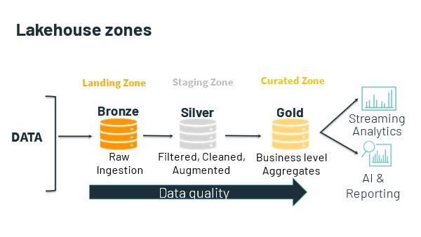
It all starts with the data lake. Again, the data lakehouse is a higher-level abstraction superimposed over the data in the lake. The lake usually consists of several zones, the names, and purposes of which vary according to implementation. At a minimum, Lakehouse consist of the following:

      • one or more ingest or landing zones for data.
      • one or more staging zones, in which experts work with and engineer data; and
      • one or more “curated” zones, in which prepared and engineered data is made available for access.

Usually, the data lake is home to all an organization’s useful data. This data is already there. So, the data lakehouse begins with query against this data where it lives.

It is in the curated (GOLD) zone of the data lake that the data lakehouse itself lives. Although it is also able to access and query against data that is stored in the lake’s other zones. In this way the data lakehouse can support not only traditional data warehousing use cases, but also innovative use cases such as data science and machine learning and artificial intelligence engineering.

The following are the advantages of the data lakehouse.

  1. More agile and less fragile than the data warehouse

Querying against data in the lake eliminates the multistep process involved in moving the data, engineering it and moving it again before loading it into the warehouse. (In extract, load, transform [ELT], data is engineered in the warehouse itself. This removes a second data movement operation.) This process is closely associated with the use of extract, transform, load (ETL) software. With the data lakehouse, instead of modeling data twice — first, during the ETL phase, and, second, to design denormalized views for a semantic layer, or to instantiate data modeling and data engineering logic in code — experts need only perform this second modeling step.

The result is less complicated (and less costly) ETL, and a less fragile data lakehouse.

  1. Query against data in place in the data lake

Querying against the data lakehouse makes sense because all an organization’s business-critical data is already there — that is, in the data lake. Data gets stored into the lake from sensors and other sources, from workload, business apps and services, from online transaction processing systems, from subscription feeds, and so on.

The strong claim is that the extra ability to query against data in the whole of the lake — that is, its staging and non-curated zones — can accelerate data delivery for time-sensitive use cases. A related claim is that it is useful to query against data in the lakehouse, even if an organization already has a data warehouse, at least for some time-sensitive use cases or practices.

The weak claim is that the lakehouse is a suitable replacement for the data warehouse.

  1. Query against relational, semi-structured, and multi-structured data

The data lakehouse sits atop the data lake, which ingests, stores and manages data of every type. Moreover, the lake’s curated zone need not be restricted solely to relational data: Organizations can store and model time series, graph, document, and other types of data there. Even though this is possible with a data warehouse, it is not cost-effective.

  1. More rapidly provision data for time-sensitive use cases

Expert users — say, scientists working on a clinical trial — can access raw trial results in the data lake’s non-curated ingest zone, or in a special zone created for this purpose. This data is not provisioned for access by all users; only expert users who understand the clinical data are permitted to access and work with it. Again, this and similar scenarios are possible because the lake functions as a central hub for data collection, access, and governance. The necessary data is already there, in the data lake’s raw or staging zones, “outside” the data lakehouse’s strictly governed zone. The organization is just giving a certain class of privileged experts early access to it.

  1. Better support for DevOps and software engineering

Unlike the classic data warehouse, the lake and the lakehouse expose various access APIs, in addition to a SQL query interface.

For example, instead of relying on ODBC/JDBC interfaces and ORM techniques to acquire and transform data from the lakehouse — or using ETL software that mandates the use of its own tool-specific programming language and IDE design facility — a software engineer can use preferred dev tools and cloud services, so long as these are also supported by team’s DevOps toolchain. The data lake/lakehouse, with its diversity of data exchange methods, its abundance of co-local compute services, and, not least, the access it affords to raw data, is arguably a better “player” in the DevOps universe than is the data warehouse. In theory, it supports a larger variety of use cases, practices, and consumers — especially expert users.

True, most RDBMSs, especially cloud PaaS RDBMSs, now support access using RESTful APIs and language-specific SDKs. This does not change the fact that some experts, particularly software engineers, are not — at all — charmed of the RDBMS.

Another consideration is that the data warehouse, especially, is a strictly governed repository. The data lakehouse imposes its own governance strictures, but the lake’s other zones can be less strictly governed. This makes the combination of the data lake + data lakehouse suitable for practices and use cases that require time-sensitive, raw, lightly prepared, so on, data (such as ML engineering).

  1. Support more and different types of analytic practices.

For expert users, the data lakehouse simplifies the task of accessing and working with raw or semi-/multi-structured data.

Data scientists, ML, and AI engineers, and, not least, data engineers can put data into the lake, acquire data from it, and take advantage of its co-locality with an assortment of intra-cloud compute services to engineer data. Experts need not use SQL; rather, they can work with their preferred languages, libraries, services and tools (notebooks, editors, and favorite CLI shells). They can also use their preferred conceptual vocabularies. So, for example, experts can build and work with data pipelines, as distinct to designing ETL jobs. In place of an ETL tool, they can use a tool such as Apache Airflow to schedule, orchestrate, and monitor workflows.

Summary

It is impossible to untie the value and usefulness of the data lakehouse from that of the data lake. In theory, the combination of the two — that is, the data lakehouse layered atop the data lake — outperforms the usefulness, flexibility, and capabilities of the data warehouse. The discussion above sometimes refers separately to the data lake and to the data lakehouse. What is usually, however, is the co-locality of the data lakehouse with the data lake — the “data lake/house,” if you like.


Bigdata File Formats Support on Dell EMC ECS 3.6

This article describes the Dell EMC ECS’s support for Apache Hadoop file formats in terms of disk space utilization. To determine this, we will use Apache Hive service to create and store different file format tables and analyze the disk space utilization by each table on the ECS storage.

Apache Hive supports several familiar file formats used in Apache Hadoop. Hive can load and query different data files created by other Hadoop components such as PIG, Spark, MapReduce, etc. In this article, we will check Apache Hive file formats such as TextFile, SequenceFIle, RCFile, AVRO, ORC and Parquet formats. Cloudera Impala also supports these file formats.

To begin with, let us understand a bit about these Bigdata File formats. Different file formats and compression codes work better for different data sets in Hadoop, the main objective of this article is to determine their supportability on DellEMC ECS storage which is a S3 compatible object store for Hadoop cluster.

Following are the Hadoop file formats

Test File: This is a default storage format. You can use the text format to interchange the data with another client application. The text file format is very common for most of the applications. Data is stored in lines, with each line being a record. Each line is terminated by a newline character(\n).

The test format is a simple plane file format. You can use the compression (BZIP2) on the text file to reduce the storage spaces.

Sequence File: These are Hadoop flat files that store values in binary key-value pairs. The sequence files are in binary format and these files can split. The main advantage of using the sequence file is to merge two or more files into one file.

RC File: This is a row columnar file format mainly used in Hive Datawarehouse, offers high row-level compression rates. If you have a requirement to perform multiple rows at a time, then you can use the RCFile format. The RCFile is very much like the sequence file format. This file format also stores the data as key-value pairs.

AVRO File: AVRO is an open-source project that provides data serialization and data exchange services for Hadoop. You can exchange data between the Hadoop ecosystem and a program written in any programming language. Avro is one of the popular file formats in Big Data Hadoop based applications.

ORC File: The ORC file stands for Optimized Row Columnar file format. The ORC file format provides a highly efficient way to store data in the Hive table. This file system was designed to overcome limitations of the other Hive file formats. The Use of ORC files improves performance when Hive is reading, writing, and processing data from large tables.

More information on the ORC file format: https://cwiki.apache.org/confluence/display/Hive/LanguageManual+ORC

Parquet File: Parquet is a column-oriented binary file format. The parquet is highly efficient for the types of large-scale queries. Parquet is especially good for queries scanning particular columns within a particular table. The Parquet table uses compression Snappy, gzip; currently Snappy by default.

More information on the Parquet file format: https://parquet.apache.org/documentation/latest/

Please note for below testing Cloudera CDP Private Cloud Base 7.1.6 Hadoop cluster is used.

Disk Space Utilization on Dell EMC ECS

What is the space on the disk that is used for these formats in Hadoop on Dell EMC ECS? Saving on disk space is always a good thing, but it can be hard to calculate exactly how much space you will be used with compression. Every file and data set is different, and the data inside will always be a determining factor for what type of compression you’ll get. The text will compress better than binary data. Repeating values and strings will compress better than pure random data, and so forth.

As a simple test, we took the 2008 data set from http://stat-computing.org/dataexpo/2009/the-data.html. The compressed bz2 download measures at 108.5 Mb, and uncompressed at 657.5 Mb. We then uploaded the data to Dell EMC ECS through s3a protocol, and created an external table on top of the uncompressed data set:

Copy the original dataset to Hadoop cluster
[root@hop-kiran-n65 ~]# ll
total 111128
-rwxr-xr-x 1 root root 113753229 May 28 02:25 2008.csv.bz2
-rw-------. 1 root root 1273 Oct 31 2020 anaconda-ks.cfg
-rw-r--r--. 1 root root 36392 Dec 15 07:48 docu99139
[root@hop-kiran-n65 ~]# hadoop fs -put ./2008.csv.bz2 s3a://hive.ecs.bucket/diff_file_format_db/bz2/
[root@hop-kiran-n65 ~]# hadoop fs -ls s3a://hive.ecs.bucket/diff_file_format_db/bz2/
Found 1 items
-rw-rw-rw- 1 root root 113753229 2021-05-28 02:00 s3a://hive.ecs.bucket/diff_file_format_db/bz2/2008.csv.bz2
[root@hop-kiran-n65 ~]#
From Hadoop Compute Node, create a database with data location on ECS bucket and create an external table for the flights data uploaded to ECS bucket location.
DROP DATABASE IF EXISTS diff_file_format_db CASCADE;

CREATE database diff_file_format_db COMMENT 'Holds all the tables data on ECS bucket' LOCATION 's3a://hive.ecs.bucket/diff_file_format_db' ;
USE diff_file_format_db;

Create external table flight_arrivals_txt_bz2 (
year int,
month int,
DayofMonth int,
DayOfWeek int,
DepTime int,
CRSDepTime int,
ArrTime int,
CRSArrTime int,
UniqueCarrier string,
FlightNum int,
TailNum string,
ActualElapsedTime int,
CRSElapsedTime int,
AirTime int,
ArrDelay int,
DepDelay int,
Origin string,
Dest string,
Distance int,
TaxiIn int,
TaxiOut int,
Cancelled int,
CancellationCode int,
Diverted int,
CarrierDelay string,
WeatherDelay string,
NASDelay string,
SecurityDelay string,
LateAircraftDelay string
)
ROW FORMAT DELIMITED
FIELDS TERMINATED BY ','
STORED AS TEXTFILE
location 's3a://hive.ecs.bucket/diff_file_format_db/bz2/';
The total number of records in this master table is
select count(*) from flight_arrivals_txt_bz2 ;

+----------+
|   _c0    |
+----------+
| 7009728  |
+----------+
Similarly, create different file format tables using the master table

To create different file formats files by simply specifying ‘STORED AS FileFormatName’ option at the end of a CREATE TABLE Command.

Create external table flight_arrivals_external_orc stored as ORC as select * from flight_arrivals_txt_bz2;
Create external table flight_arrivals_external_parquet stored as Parquet as select * from flight_arrivals_txt_bz2;
Create external table flight_arrivals_external_textfile stored as textfile as select * from flight_arrivals_txt_bz2;
Create external table flight_arrivals_external_sequencefile stored as sequencefile as select * from flight_arrivals_txt_bz2;
Create external table flight_arrivals_external_rcfile stored as rcfile as select * from flight_arrivals_txt_bz2;
Create external table flight_arrivals_external_avro stored as avro as select * from flight_arrivals_txt_bz2;
Disk space utilization of the tables

Now, let us compare the disk usage on ECS of all the files from Hadoop compute nodes.

[root@hop-kiran-n65 ~]# hadoop fs -du -h s3a://hive.ecs.bucket/diff_file_format_db/ | grep flight_arrivals
597.7 M 597.7 M s3a://hive.ecs.bucket/diff_file_format_db/flight_arrivals_external_avro
93.5 M 93.5 M s3a://hive.ecs.bucket/diff_file_format_db/flight_arrivals_external_orc
146.6 M 146.6 M s3a://hive.ecs.bucket/diff_file_format_db/flight_arrivals_external_parquet
403.1 M 403.1 M s3a://hive.ecs.bucket/diff_file_format_db/flight_arrivals_external_rcfile
751.1 M 751.1 M s3a://hive.ecs.bucket/diff_file_format_db/flight_arrivals_external_sequencefile
670.7 M 670.7 M s3a://hive.ecs.bucket/diff_file_format_db/flight_arrivals_external_textfile
[root@hop-kiran-n65 ~]#

Summary

From the below table we can conclude that Dell EMC ECS as S3 storage supports all the Hadoop file formats and provides the same disk utilization as with the traditional HDFS storage.

Compressed Percentage lower is batter and Compression ratio higher is better.

Format
Size
Compressed%
Compressed Ratio
CSV (Text) 670.7 M
BZ2 108.5 M 16.18% 83.82%
ORC 93.5 M 13.94% 86.06%
Parquet 146.6 M 21.85% 78.15%
RC FIle 403.1 M 60.10% 39.90%
AVRO 597.7 M 89.12% 10.88%
Sequence 751.1 M 111.97% -11.87%

Here the default settings and values were used to create all the different file format tables, there were no other optimizations done for this testing. Each file format ships with many options and optimizations to compress the data, only the defaults that ship CDP pvt cloud base 7.1.6 were used.


HDFS Service not enabled by default in 9.0 OneFS – java.net.ConnectException: Connection refused

In OneFS 9.0 by default Services are not enabled by default, this also includes NFS, SMB, S3 and HDFS.

When attempting to use HDFS against an 9.0 cluster, the Hadoop client may see the following error on all HDFS access.

[cdh6-1-user1@centos-10 ~]$ hadoop fs -ls /

ls: Call From centos-10.foo.com/10.246.156.21 to cdh6.foo.com:8020 failed on connection exception: java.net.ConnectException: Connection refused; For more details see:  http://wiki.apache.org/hadoop/ConnectionRefused


This is because the HDFS service is not enabled on HDFS and therefore connections are refused.

When looking at the cluster we see the Service is Disabled as by design.

# isi services -al | grep hdfs

Available Services:

  hdfs                 HDFS Server                              Disabled


But when looking at the WebUI or the CLI, this misleading as the Service appears enabled

cascade-1# isi hdfs settings view

                 Service: Yes

      Default Block Size: 128M

   Default Checksum Type: none

     Authentication Mode: simple_only

          Root Directory: /ifs/data

         WebHDFS Enabled: Yes

           Ambari Server:

         Ambari Namenode:

             ODP Version:

    Data Transfer Cipher: none

Ambari Metrics Collector:

To enable the Service and allow HDFS connectivity, enable the hdfs service directly from the CLI.

isi services hdfs enable

# isi services -al | grep hdfs

Available Services:

  hdfs                 HDFS Server                              Enabled


Now the service is Enabled, HDFS operation can occur.

[cdh6-1-user1@centos-10 ~]$ hadoop fs -ls /

Found 11 items

-rwxrwxrwx   3 root         wheel               1 2020-02-20 11:38 /1.txt

-rwxrwxrwx   3 hbase        yarn               17 2020-02-20 11:31 /THIS_IS_ISILON_zone1-hadoop.txt

drwxr-xr-x   - hbase        hbase               0 2020-05-26 14:19 /_hbase

-rw-r--r--   3 root         wheel               0 2020-09-14 17:46 /cdh6_zone.txt

drwxr-xr-x   - hbase        hbase               0 2020-08-11 11:47 /hbase

-rw-r--r--   3 root         wheel               0 2020-09-14 17:46 /isilon_9.txt

drwxrwxrwx   - cdh6-1-user1 supergroup          0 2020-03-10 15:20 /nfs

drwxrwxr-x   - solr         solr                0 2019-12-12 13:29 /solr

drwxrwxrwt   - hdfs         supergroup          0 2019-12-12 13:29 /tmp

drwxr-xr-x   - hdfs         supergroup          0 2020-01-15 12:32 /user

-rw-r--r--   3 root         wheel               0 2020-09-14 17:47 /zone-3.txt


As an FYI: NFS, SMB & S3 are also Disabled by default in 9.0, but the Service checkbox/status can be managed via the WebUI Service enabled box on these services.

# isi services -al | grep smb

   smb                  SMB Service                              Disabled

Enable the Service via the WebUI:

# isi services -al | grep smb

   smb                  SMB Service                              Enabled

Dell EMC ECS IAM and Hadoop S3A Implementation

This paper describes basic information on IAM features with Dell EMC ECS and step by step process to configure ECS with AD FS to determine SAML support features, that allow the Hadoop administrator to setup access policies to control access to S3A Hadoop data.

https://www.dellemc.com/resources/en-us/asset/white-papers/products/storage/h18420-dell-emc-ecs-iam-and-hadoop-s3a-implementation.pdf


HDP Upgrade and Transparent Data Encryption(TDE) support on Isilon OneFS 8.2

HDP Upgrade and Transparent Data Encryption support on Isilon OneFS 8.2

The objective of this testing is to demonstrate the Hortonworks HDP upgrade from HDP 2.6.5 to HDP 3.1 , during which Transparent Data Encryption(TDE) KMS keys and configuration are ported to OneFS Service from HDFS service after upgrade accurately, this facilitates Hadoop user to leverage TDE support on OneFS 8.2 straight out of the box after upgrade without any changes to the TDE/KMS configurations.

HDFS Transparent Data Encryption

The primary motivation of Transparent Data Encryption on HDFS is to support both end-to-end on wire and at rest encryption for data without any modification to the user application. The TDE scheme adds an additional layer of data protection by storing the decryption keys for files on a separate key management server. This separation of keys and data guarantees that even if the HDFS service is completely compromised the files cannot be decrypted without also compromising the keystore.

Concerns and Risks

The primary concern with TDE is mangling/losing Encrypted Data Encryption Keys (EDEKs) which are unique to each file in an Encryption Zone and are necessary to decrypt the data within. If this occurs, the customer’s data will be lost (DL). A secondary concern is managing Encryption Zone Keys (EKs) which are unique to each Encryption Zone and are associated with the root directory of each Zone. Losing/Mangling the EK would result in data unavailability (DU) for the customer and would require admin intervention to remedy. Finally, we need to make sure that EDEKs are not reused in anyway as this would weaken the security of TDE. Otherwise, there is little to no risk to existing or otherwise unencrypted data since TDE only works within Encryption Zones which are not currently supported.

Hortonworks HDP 2.6.5 on Isilon OneFS 8.2

To install HDP 2.6.5 on OneFS 8.2 by following the install guide.

Note: In install, the document is for OneFS 8.1.2 in which hdfs user is mapped to root in the Isilon setting, which is not required on OneFS 8.2, but need to create a new role to the hdfs user to backup/restore RWX access on the file system.

OneFS 8.2  [New Steps to be new role to the hdfs access zone]

hop-isi-dd-3# isi auth roles create --name=BackUpAdmin --description="Bypass FS permissions" --zone=hdp
hop-isi-dd-3# isi auth roles modify BackupAdmin --add-priv=ISI_PRIV_IFS_RESTORE --zone=hdp
hop-isi-dd-3# isi auth roles modify BackupAdmin --add-priv=ISI_PRIV_IFS_BACKUP --zone=hdp
hop-isi-dd-3# isi auth roles view BackUpAdmin --zone=hdp
Name: BackUpAdmin
Description: Bypass FS permissions
    Members: -
Privileges
ID: ISI_PRIV_IFS_BACKUP
      Read Only: True

ID: ISI_PRIV_IFS_RESTORE
      Read Only: True

hop-isi-dd-3# isi auth roles modify BackupAdmin --add-user=hdfs --zone=hdp


----- [ Optional:: Flush the auth mapping and cache to make hdfs take effect immediately]
hop-isi-dd-3# isi auth mapping flush --all
hop-isi-dd-3# isi auth cache flush --all
-----


1. After HDP 2.6.5 is installed on OneFS 8.2 following the install guide and above steps to add hdfs user backup/restore role. Install Ranger and Ranger KMS services, run service check on all the services to make sure the cluster is healthy and functional.


2. On the Isilon make sure hdfs access zone and hdfs user role are setup as required.

Isilon version

hop-isi-dd-3# isi version
Isilon OneFS v8.2.0.0 B_8_2_0_0_007(RELEASE): 0x802005000000007:Thu Apr  4 11:44:04 PDT 2019 root@sea-build11-04:/b/mnt/obj/b/mnt/src/amd64.amd64/sys/IQ.amd64.release   FreeBSD clang version 3.9.1 (tags/RELEASE_391/final 289601) (based on LLVM 3.9.1)
hop-isi-dd-3#
HDFS user role setup
hop-isi-dd-3# isi auth roles view BackupAdmin --zone=hdp
Name: BackUpAdmin
Description: Bypass FS permissions
Members: hdfs
Privileges
ID: ISI_PRIV_IFS_BACKUP
Read Only: True

ID: ISI_PRIV_IFS_RESTORE
Read Only: True
hop-isi-dd-3#


Isilon HDFS setting
hop-isi-dd-3# isi hdfs settings view --zone=hdp
Service: Yes
Default Block Size: 128M
Default Checksum Type: none
Authentication Mode: all
Root Directory: /ifs/data/zone1/hdp
WebHDFS Enabled: Yes
Ambari Server:
Ambari Namenode: kb-hdp-z1.hop-isi-dd.solarch.lab.emc.com
ODP Version:
Data Transfer Cipher: none
Ambari Metrics Collector: pipe-hdp1.solarch.emc.com
hop-isi-dd-3#


hdfs to root mapping removed from the access zone setting
hop-isi-dd-3# isi zone view hdp
Name: hdp
Path: /ifs/data/zone1/hdp
Groupnet: groupnet0
Map Untrusted:
Auth Providers: lsa-local-provider:hdp
NetBIOS Name:
User Mapping Rules:
Home Directory Umask: 0077
Skeleton Directory: /usr/share/skel
Cache Entry Expiry: 4H
Negative Cache Entry Expiry: 1m
Zone ID: 2
hop-isi-dd-3#

3. TDE Functional Testing

Primary Testing Foci

Reads and Writes: Clients with the correct permissions must always be able to reliably decrypt.

Kerberos Integration: Realistically, customers will not deploy TDE without Kerberos. [ In this testing Kerberos is not integrated]

TDE Configurations

HDFS TDE Setup
a. Create an encryption zone (EZ) key

Hadoop key create <keyname>

User “keyadmin” has privileges to create, delete, rollover, set key material, get, get keys, get metadata, generate EEK and Decrypt EEK. These privileges are controlled in Ranger web UI, login as keyadmin / <password> and setup these privileges.

[root@pipe-hdp1 ~]# su keyadmin
bash-4.2$ whoami
keyadmin

bash-4.2$ hadoop key create key_a
key_a has been successfully created with options Options{cipher='AES/CTR/NoPadding', bitLength=128, description='null', attributes=null}.
KMSClientProvider[http://pipe-hdp1.solarch.emc.com:9292/kms/v1/] has been updated.

bash-4.2$ hadoop key create key_a
key_a has been successfully created with options Options{cipher='AES/CTR/NoPadding', bitLength=128, description='null', attributes=null}.
KMSClientProvider[http://pipe-hdp1.solarch.emc.com:9292/kms/v1/] has been updated.

bash-4.2$
bash-4.2$ hadoop key list
Listing keys for KeyProvider: KMSClientProvider[http://pipe-hdp1.solarch.emc.com:9292/kms/v1/]
key_data
key_b
key_a
bash-4.2$
Note:: New Keys can also be created from Ranger KMS UI.


OneFS TDE Setup

a. Configure KMS URL in the Isilon OneFS CLI

isi hdfs crypto settings modify –kms-url=<url-string> –zone=<hdfs-zone-name> -v

isi hdfs crypto settings view –zone=<hdfs-zone-name>

hop-isi-dd-3# isi hdfs crypto settings view --zone=hdp
Kms Url: http://pipe-hdp1.solarch.emc.com:9292

hop-isi-dd-3#


b. Create a new directory in Isilon OneFS CLI under the Hadoop zone that needs to be encryption zone

mkdir /ifs/hdfs/<new-directory-name>

hop-isi-dd-3# mkdir /ifs/data/zone1/hdp/data_a

hop-isi-dd-3# mkdir /ifs/data/zone1/hdp/data_b
c. After new directory created, create encryption zone by assigning encryption key and directory path

isi hdfs crypto encryption-zones create –path=<new-directory-path> –key-name=<key-created-via-hdfs> –zone=<hdfs-zone-name> -v

hop-isi-dd-3# isi hdfs crypto encryption-zones create --path=/ifs/data/zone1/hdp/data_a --key-name=key_a --zone=hdp -v
Create encryption zone named /ifs/data/zone1/hdp/data_a, with key_a

hop-isi-dd-3# isi hdfs crypto encryption-zones create --path=/ifs/data/zone1/hdp/data_b --key-name=key_b --zone=hdp -v
Create encryption zone named /ifs/data/zone1/hdp/data_b, with key_b
NOTE:
    1. Encryption keys need to be created from hdfs client
    2. Need KMS store to manage keys example Ranger KMS
    3. Encryption zones can be created only on Isilon with CLI
    4. Creating an encryption zone from hdfs client fails with Unknown RPC RemoteException.

TDE Setup Validation

On HDFS Cluster

a. Verify the same from hdfs client   [Path is listed from the hdfs root dir]

hdfs crypto -listZones

bash-4.2$ hdfs crypto -listZones
/data_a  key_a
/data_b  key_b

On Isilon Cluster

a. List the encryption zones on Isilon                                            [Path is listed from the Isilon root path]

hdfs crypto -listZones

bash-4.2$ hdfs crypto -listZones
/data_a  key_a
/data_b  key_b


TDE Functional Testing

Authorize users to the EZ and KMS Keys

Ranger KMS UI

a. Login into Ranger KMS UI using keyadmin / <password>


b. Create 2 new policies to assign users (yarn, hive) to key_a and (mapred, hive) to key_b with the Get, Get Keys, Get Metadata, Generate EEK and Decrypt EEK permissions.


TDE HDFS Client Testing

a. Create sample files, copy it to respective EZs and access them from respective users.
/data_a EZ associated with key_a and only yarn, hive users have permissions
bash-4.2$ whoami
yarn
bash-4.2$ echo "YARN user test file, can you read this?" > yarn_test_file
bash-4.2$ rm -rf yarn_test_fil
bash-4.2$ hadoop fs -put yarn_test_file /data_a/
bash-4.2$ hadoop fs -cat /data_a/yarn_test_file
YARN user test file, can you read this?
bash-4.2$ whoami
yarn
bash-4.2$ exit
exit

[root@pipe-hdp1 ~]# su mapred
bash-4.2$ hadoop fs -cat /data_a/yarn_test_file
cat: User:mapred not allowed to do 'DECRYPT_EEK' on 'key_a'

bash-4.2$
/data_b EZ associated with key_b and only mapred, hive users have permissions
bash-4.2$ whoami
mapred
bash-4.2$ echo "MAPRED user test file, can you read this?" > mapred_test_file
bash-4.2$ hadoop fs -put mapred_test_file /data_b/
bash-4.2$ hadoop fs -cat /data_b/mapred_test_file
MAPRED user test file, can you read this?
bash-4.2$ exit
exit

[root@pipe-hdp1 ~]# su yarn
bash-4.2$ hadoop fs -cat /data_b/mapred_test_file
cat: User:yarn not allowed to do 'DECRYPT_EEK' on 'key_b'

bash-4.2$

User hive has permission to decrypt both keys i.e. ca access both EZs
USER user with decrypt privilege [HIVE]
[root@pipe-hdp1 ~]# su hive
bash-4.2$ pwd
/root
bash-4.2$ hadoop fs -cat /data_b/mapred_test_file
MAPRED user test file, can you read this?
bash-4.2$  hadoop fs -cat /data_a/yarn_test_file
YARN user test file, can you read this?
bash-4.2$


Sample distcp to copy data between EZs.
bash-4.2$ hadoop distcp -skipcrccheck -update /data_a/yarn_test_file /data_b/
19/05/20 21:20:02 INFO tools.DistCp: Input Options: DistCpOptions{atomicCommit=false, syncFolder=true, deleteMissing=false, ignoreFailures=false, overwrite=false, append=false, useDiff=false, fromSnapshot=null, toSnapshot=null, skipCRC=true, blocking=true, numListstatusThreads=0, maxMaps=20, mapBandwidth=100, sslConfigurationFile='null', copyStrategy='uniformsize', preserveStatus=[], preserveRawXattrs=false, atomicWorkPath=null, logPath=null, sourceFileListing=null, sourcePaths=[/data_a/yarn_test_file], targetPath=/data_b, targetPathExists=true, filtersFile='null', verboseLog=false}
19/05/20 21:20:03 INFO client.RMProxy: Connecting to ResourceManager at pipe-hdp1.solarch.emc.com/10.246.156.91:8050
19/05/20 21:20:03 INFO client.AHSProxy: Connecting to Application History server at pipe-hdp1.solarch.emc.com/10.246.156.91:10200
"""
"""
19/05/20 21:20:04 INFO mapreduce.Job: Running job: job_1558336274787_0003
19/05/20 21:20:12 INFO mapreduce.Job: Job job_1558336274787_0003 running in uber mode : false
19/05/20 21:20:12 INFO mapreduce.Job: map 0% reduce 0%
19/05/20 21:20:18 INFO mapreduce.Job: map 100% reduce 0%
19/05/20 21:20:18 INFO mapreduce.Job: Job job_1558336274787_0003 completed successfully
19/05/20 21:20:18 INFO mapreduce.Job: Counters: 33
File System Counters
FILE: Number of bytes read=0
FILE: Number of bytes written=152563
FILE: Number of read operations=0
FILE: Number of large read operations=0
FILE: Number of write operations=0
HDFS: Number of bytes read=426
HDFS: Number of bytes written=40
HDFS: Number of read operations=15
HDFS: Number of large read operations=0
HDFS: Number of write operations=4
Job Counters
Launched map tasks=1
Other local map tasks=1
Total time spent by all maps in occupied slots (ms)=4045
Total time spent by all reduces in occupied slots (ms)=0
Total time spent by all map tasks (ms)=4045
Total vcore-milliseconds taken by all map tasks=4045
Total megabyte-milliseconds taken by all map tasks=4142080
Map-Reduce Framework
Map input records=1
Map output records=0
Input split bytes=114
Spilled Records=0
Failed Shuffles=0
Merged Map outputs=0
GC time elapsed (ms)=91
CPU time spent (ms)=2460
Physical memory (bytes) snapshot=290668544
Virtual memory (bytes) snapshot=5497425920
Total committed heap usage (bytes)=196083712
File Input Format Counters
Bytes Read=272
File Output Format Counters
Bytes Written=0
org.apache.hadoop.tools.mapred.CopyMapper$Counter
BYTESCOPIED=40
BYTESEXPECTED=40
COPY=1
bash-4.2$
bash-4.2$ hadoop fs -ls /data_b/
Found 2 items
-rwxrwxr-x   3 mapred hadoop         42 2019-05-20 04:24 /data_b/mapred_test_file
-rw-r--r--   3 hive   hadoop         40 2019-05-20 21:20 /data_b/yarn_test_file
bash-4.2$ hadoop fs -cat /data_b/yarn_test_file
YARN user test file, can you read this?

bash-4.2$

Hadoop user without permission
bash-4.2$ hadoop fs -put test_file /data_a/
put: User:hdfs not allowed to do 'DECRYPT_EEK' on 'key_A'
19/05/20 02:35:10 ERROR hdfs.DFSClient: Failed to close inode 4306114529
org.apache.hadoop.ipc.RemoteException(java.io.FileNotFoundException): File does not exist: /data_a/test_file._COPYING_ (inode 4306114529)

TDE OneFS CLI Testing

EZ on Isilon EZ, no user has access to read the file
hop-isi-dd-3# whoami
root
hop-isi-dd-3# cat data_a/yarn_test_file

▒?Tm@DIc▒▒B▒▒>\Qs▒:[VzC▒▒Rw^<▒▒▒▒▒8H#


hop-isi-dd-3% whoami
yarn
hop-isi-dd-3% cat data_a/yarn_test_file

▒?Tm@DIc▒▒B▒▒>\Qs▒:[VzC▒▒Rw^<▒▒▒▒▒8H%

Upgrade the HDP to the latest version, following the upgrade process blog.

After upgrade make sure all the services are up running and pass the service check.

HDFS service will be replaced with OneFS service, under OneFS service configuration make sure KMS related properties are ported successfully.

Login into KMS UI and check the policies are intact after upgrade [ Note after upgrading new “Policy Labels” column added]


TDE validate existing configuration and keys after HDP 3.1 upgrade

TDE HDFS client testing existing configuration and keys

a. List the KMS provider and key to check they are intact after the upgrade
[root@pipe-hdp1 ~]# su hdfs
bash-4.2$ hadoop key list
Listing keys for KeyProvider: org.apache.hadoop.crypto.key.kms.LoadBalancingKMSClientProvider@2f54a33d
key_b
key_a
key_data

bash-4.2$ hdfs crypto -listZones
/data    key_data
/data_a  key_a
/data_b  key_b

b. Create sample files, copy it to respective EZs and access them from respective users
[root@pipe-hdp1 ~]# su yarn
bash-4.2$ cd
bash-4.2$ pwd
/home/yarn
bash-4.2$ echo "YARN user testfile after upgrade to hdp3.1, can you read this?" > yarn_test_file_2
bash-4.2$ hadoop fs -put yarn_test_file_2 /data_a/
bash-4.2$ hadoop fs -cat /data_a/yarn_test_file_2
YARN user testfile after upgrade to hdp3.1, can you read this?

bash-4.2$
[root@pipe-hdp1 ~]# su mapred
bash-4.2$ cd
bash-4.2$ pwd
/home/mapred
bash-4.2$ echo "MAPRED user testfile after upgrade to hdp3.1, can you read this?" > mapred_test_file_2
bash-4.2$ hadoop fs -put mapred_test_file_2 /data_b/
bash-4.2$ hadoop fs -cat /data_b/mapred_test_file_2
MAPRED user testfile after upgrade to hdp3.1, can you read this?

bash-4.2$
[root@pipe-hdp1 ~]# su yarn
bash-4.2$ hadoop fs -cat /data_b/mapred_test_file_2
cat: User:yarn not allowed to do 'DECRYPT_EEK' on 'key_b'

bash-4.2$
[root@pipe-hdp1 ~]# su hive
bash-4.2$ hadoop fs -cat /data_a/yarn_test_file_2
YARN user testfile after upgrade to hdp3.1, can you read this?

bash-4.2$ hadoop fs -cat /data_b/mapred_test_file_2
MAPRED user testfile after upgrade to hdp3.1, can you read this?

bash-4.2$
bash-4.2$ hadoop distcp -skipcrccheck -update /data_a/yarn_test_file_2 /data_b/
19/05/21 05:23:38 INFO tools.DistCp: Input Options: DistCpOptions{atomicCommit=false, syncFolder=true, deleteMissing=false, ignoreFailures=false, overwrite=false, append=false, useDiff=false, useRdiff=false, fromSnapshot=null, toSnapshot=null, skipCRC=true, blocking=true, numListstatusThreads=0, maxMaps=20, mapBandwidth=0.0, copyStrategy='uniformsize', preserveStatus=[BLOCKSIZE], atomicWorkPath=null, logPath=null, sourceFileListing=null, sourcePaths=[/data_a/yarn_test_file_2], targetPath=/data_b, filtersFile='null', blocksPerChunk=0, copyBufferSize=8192, verboseLog=false}, sourcePaths=[/data_a/yarn_test_file_2], targetPathExists=true, preserveRawXattrsfalse
19/05/21 05:23:38 INFO client.RMProxy: Connecting to ResourceManager at pipe-hdp1.solarch.emc.com/10.246.156.91:8050
19/05/21 05:23:38 INFO client.AHSProxy: Connecting to Application History server at pipe-hdp1.solarch.emc.com/10.246.156.91:10200
"
19/05/21 05:23:54 INFO mapreduce.Job: map 0% reduce 0%
19/05/21 05:24:00 INFO mapreduce.Job: map 100% reduce 0%
19/05/21 05:24:00 INFO mapreduce.Job: Job job_1558427755021_0001 completed successfully
19/05/21 05:24:00 INFO mapreduce.Job: Counters: 36
"
Bytes Copied=63
Bytes Expected=63
Files Copied=1

bash-4.2$ hadoop fs -ls /data_b/
Found 4 items
-rwxrwxr-x   3 mapred hadoop         42 2019-05-20 04:24 /data_b/mapred_test_file
-rw-r--r--   3 mapred hadoop         65 2019-05-21 05:21 /data_b/mapred_test_file_2
-rw-r--r--   3 hive   hadoop         40 2019-05-20 21:20 /data_b/yarn_test_file
-rw-r--r--   3 hive   hadoop         63 2019-05-21 05:23 /data_b/yarn_test_file_2

bash-4.2$ hadoop fs -cat /data_b/yarn_test_file_2
YARN user testfile after upgrade to hdp3.1, can you read this?

bash-4.2$ hadoop fs -cat /data_b/yarn_test_file_2
YARN user testfile after upgrade to hdp3.1, can you read this?

bash-4.2$
TDE OneFS client testing existing configuration and keys
a. List the KMS provider and key to check they are intact after upgrade
hop-isi-dd-3# isi hdfs crypto settings view --zone=hdp
Kms Url: http://pipe-hdp1.solarch.emc.com:9292
hop-isi-dd-3# isi hdfs crypto encryption-zones list
Path                       Key Name
------------------------------------
/ifs/data/zone1/hdp/data   key_data
/ifs/data/zone1/hdp/data_a key_a
/ifs/data/zone1/hdp/data_b key_b
------------------------------------
Total: 3

hop-isi-dd-3#
b. Permission to access previous created EZs
hop-isi-dd-3# cat data_b/yarn_test_file_2
3▒
▒{&▒{<N▒7▒      ,▒▒l▒n.▒▒▒bz▒6▒ ▒G▒_▒l▒Ieñ+
▒t▒▒N^▒ ▒# hop-isi-dd-3# whoami
root
hop-isi-dd-3#

TDE validate new configuration and keys after HDP 3.1 upgrade

TDE HDFS Client new keys setup

a. Create new keys and list
bash-4.2$ hadoop key create up_key_a
up_key_a has been successfully created with options Options{cipher='AES/CTR/NoPadding', bitLength=128, description='null', attributes=null}.
org.apache.hadoop.crypto.key.kms.LoadBalancingKMSClientProvider@11bd0f3b has been updated.

bash-4.2$ hadoop key create up_key_b
up_key_b has been successfully created with options Options{cipher='AES/CTR/NoPadding', bitLength=128, description='null', attributes=null}.
org.apache.hadoop.crypto.key.kms.LoadBalancingKMSClientProvider@11bd0f3b has been updated.

bash-4.2$ hadoop key list
Listing keys for KeyProvider: org.apache.hadoop.crypto.key.kms.LoadBalancingKMSClientProvider@2f54a33d
key_b
key_a
key_data
up_key_b
up_key_a

bash-4.2$

b. After EZs created from OneFS CLI check the zones reflect from HDFS client
bash-4.2$ hdfs crypto -listZones
/data       key_data
/data_a     key_a
/data_b     key_b
/up_data_a  up_key_a
/up_data_b  up_key_b


TDE OneFS Client new encryption zone setup

a. Create new EZ from OneFS CLI

HOP-ISI-DD-3# ISI HDFS CRYPTO ENCRYPTION-ZONES CREATE --PATH=/IFS/DATA/ZONE1/HDP/UP_DATA_A --KEY-NAME=UP_KEY_A --ZONE=HDP -V
Create encryption zone named /ifs/data/zone1/hdp/up_data_a, with up_key_a
hop-isi-dd-3# isi hdfs crypto encryption-zones create --path=/ifs/data/zone1/hdp/up_data_b --key-name=up_key_b --zone=hdp -v
Create encryption zone named /ifs/data/zone1/hdp/up_data_b, with up_key_b

hop-isi-dd-3# isi hdfs crypto encryption-zones list
Path                          Key Name
---------------------------------------
/ifs/data/zone1/hdp/data key_data
/ifs/data/zone1/hdp/data_a    key_a
/ifs/data/zone1/hdp/data_b    key_b
/ifs/data/zone1/hdp/up_data_a up_key_a
/ifs/data/zone1/hdp/up_data_b up_key_b
---------------------------------------
Total: 5

hop-isi-dd-3#

Create 2 new policies to assign users (yarn, hive) to up_key_a and (mapred, hive) to up_key_b with the Get, Get Keys, Get Metadata, Generate EEK and Decrypt EEK permissions.

TDE HDFS Client testing on upgraded HDP 3.1

a. Create sample files, copy it to respective EZs and access them from respective users

/up_data_a EZ associated with up_key_a and only yarn, hive users have permissions

[root@pipe-hdp1 ~]# su yarn
bash-4.2$ echo "After HDP Upgrade to HDP 3.1, YARN user, Creating this file" > up_yarn_test_file
bash-4.2$ hadoop fs -put up_yarn_test_file /up_data_a/
bash-4.2$ hadoop fs -cat /up_data_a/up_yarn_test_file
After HDP Upgrade to HDP 3.1, YARN user, Creating this file

bash-4.2$ hadoop fs -cat /up_data_b/up_mapred_test_file
cat: User:yarn not allowed to do 'DECRYPT_EEK' on 'up_key_b'
bash-4.2$

/up_data_b EZ associated with up_key_b and only mapred, hive users have permissions

[root@pipe-hdp1 ~]# su mapred
bash-4.2$ cd
bash-4.2$ echo "After HDP Upgrade to HDP 3.1, MAPRED user, Creating this file" > up_mapred_test_file
bash-4.2$ hadoop fs -put up_mapred_test_file /up_data_b/
bash-4.2$ hadoop fs -cat /up_data_b/up_mapred_test_file
After HDP Upgrade to HDP 3.1, MAPRED user, Creating this file

bash-4.2$


User hive has permission to decrypt both keys i.e. ca access both EZs

USER user with decrypt privilege [HIVE]

[root@pipe-hdp1 ~]# su hive
bash-4.2$ hadoop fs -cat /up_data_b/up_mapred_test_file
After HDP Upgrade to HDP 3.1, MAPRED user, Creating this file

bash-4.2$ hadoop fs -cat /up_data_a/up_yarn_test_file
After HDP Upgrade to HDP 3.1, YARN user, Creating this file
bash-4.2$


Sample distcp to copy data between EZs.

bash-4.2$ hadoop distcp -skipcrccheck -update /up_data_a/up_yarn_test_file /up_data_b/
19/05/22 04:48:21 INFO tools.DistCp: Input Options: DistCpOptions{atomicCommit=false, syncFolder=true, deleteMissing=false, ignoreFailures=false, overwrite=false, append=false, useDiff=false, useRdiff=false, fromSnapshot=null, toSnapshot=null, skipCRC=true, blocking=true, numListstatusThreads=0, maxMaps=20, mapBandwidth=0.0, copyStrategy='uniformsize', preserveStatus=[BLOCKSIZE], atomicWorkPath=null, logPath=null, sourceFileListing=null, sourcePaths=[/up_data_a/up_yarn_test_file], targetPath=/up_data_b, filtersFile='null', blocksPerChunk=0, copyBufferSize=8192, verboseLog=false}, sourcePaths=[/up_data_a/up_yarn_test_file], targetPathExists=true, preserveRawXattrsfalse
"
19/05/22 04:48:23 INFO mapreduce.Job: The url to track the job: http://pipe-hdp1.solarch.emc.com:8088/proxy/application_1558505736502_0001/
19/05/22 04:48:23 INFO tools.DistCp: DistCp job-id: job_1558505736502_0001
19/05/22 04:48:23 INFO mapreduce.Job: Running job: job_1558505736502_0001
"
Bytes Expected=60
Files Copied=1

bash-4.2$ hadoop fs -ls /up_data_b/
Found 2 items
-rw-r--r--   3 mapred hadoop         62 2019-05-22 04:43 /up_data_b/up_mapred_test_file
-rw-r--r--   3 hive   hadoop         60 2019-05-22 04:48 /up_data_b/up_yarn_test_file

bash-4.2$ hadoop fs -cat /up_data_b/up_yarn_test_file
After HDP Upgrade to HDP 3.1, YARN user, Creating this file

bash-4.2$

Hadoop user without permission

bash-4.2$ hadoop fs -put test_file /data_a/
put: User:hdfs not allowed to do 'DECRYPT_EEK' on 'key_A'
19/05/20 02:35:10 ERROR hdfs.DFSClient: Failed to close inode 4306114529
org.apache.hadoop.ipc.RemoteException(java.io.FileNotFoundException): File does not exist: /data_a/test_file._COPYING_ (inode 4306114529)


TDE OneFS CLI Testing

Permissions on Isilon EZ, no user has access to read the file
hop-isi-dd-3# cat up_data_a/up_yarn_test_file
%*݊▒▒ixu▒▒▒=}▒΁▒▒h~▒7▒=_▒▒▒0▒[.-$▒:/▒Ԋ▒▒▒▒\8vf▒{F▒Sl▒▒#


Conclusion

Above testing and results prove that HDP upgrade does not break and TDE configuration and same are ported to new OneFS service after a successful upgrade.
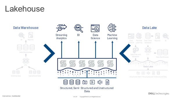
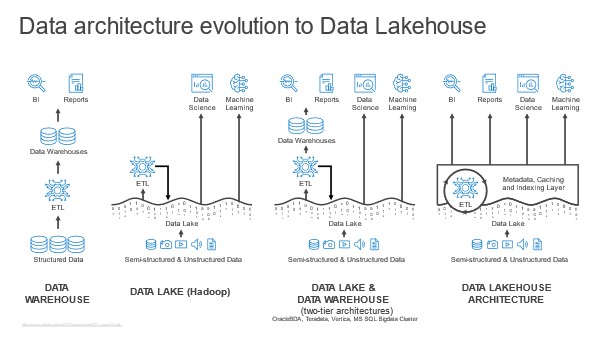
Exploring Hive LLAP using Testbench On OneFS

Short Description

Explore Hive LLAP by using Horontworks Testbench to generate data and run queries with LLAP enabled using HiveServer2 Interactive JDBC URL.

Article

The latest release of Isilon OneFS 8.1.2 delivers new capabilities and support like Apache Hadoop 3, Isilon Ambari Management pack, Apache Hive LLAP, Apache Ranger with SSL and WebHDFS. In this article, we shall explore Apache Hive LLAP using Horontworks Hive Testbench which supports LLAP. The Hive Testbench consists of a data generator and a standard set of queries typically used for benchmarking hive performance. This article describes how to generate data and run a query in beeline, with LLAP enabled.

If you don’t have a cluster already configured for LLAP, set up new HDP2.6 on Isilon OneFS from here and enable Interactive query under Ambari Server UI –> Hive –> Configs as below.

Hive Testbench setup

1. Log into the HDP client node where HIVE is installed.

2. Install and Setup Hive testbench

3. Generate 5GB of test data: [Here we shall use TPC-H Testbench]

  /If GCC not install/  yum install -y gcc

/If javac not found/ export JAVA_HOME=/usr/jdk64/jdk1.8.**** ;  export PATH=$JAVA_HOME/bin:$PATH

cd hive-testbench-hdp3/ sudo ./tpch-build.sh ./tpch-setup.sh 5


4. A MapReduce job runs to create the data and load the data into hive. This will take some time to complete. The last line in the script is:

Data loaded into database tpch_******.


Make sure all the below prerequisites are met before proceeding ahead.

1. HDP cluster up and running

2. YARN all services, Hive all services are up and running

3. Uid/gid parity and necessary directory structure maintained between HDP and OneFS

4. Interactive Query enabled.

5. Hive Testbench TPC-H database setup and data loaded.

Connecting to Interactive Service and running queries
Through Command Line

1. Log into the HDP client node where HIVE is installed and Hive Testbench setup.

2. Change to the directory where Hive Testbench is placed and into the sample-queries-tpch.

3. From Ambari Server Web UI –> HIVE Service –> Summary page, copy the HiveServer2 Interactive JDBC URL”


4. Run beeline with HiveServer2 Interactive JDBC URL with credential hive/hive.

beeline -n hive -p hive -u "jdbc:hive2://hawkeye03.kanagawa.demo:2181/;serviceDiscoveryMode=zooKeeper;zooKeeperNamespace=hiveserver2-hive2"

5. Run show databases command to check the tpch databases created during HIVE Testbench setup.

0: jdbc:hive2://hawkeye03.kanagawa.demo:2181/> show databases;

6. Switch to the tpch_flat_orc_5 databases

0: jdbc:hive2://hawkeye03.kanagawa.demo:2181/> use tpch_flat_orc_5;

7. Run the query7.sql by issuing run command as below and note down the execution time, let’s call this 1st run.

0: jdbc:hive2://hawkeye03.kanagawa.demo:2181/> !run query7.sql

To monitor LLAP functioning open HiveServer2 Interactive UI from the Ambari Server web UI –> Hive service –> Summary –> Quick Links –> HiveServer2 Interactive UI

Figure :: HiveServer2 Interactive UI

Now click on Running Instances Web URL(highlighted in above image) to go to LLAP Monitor page

On this LLAP Monitor UI, metrics to watch are Cache (use rate, Request count, Hit Rate) and System (LLAP open Files).


8. Immediate after step 7, which was 1st time query7.sql run, let us run the same query7.sql again and call it 2nd run. Monitor execution time, LLAP cache Metrics and System metrics.


Notice the drastic reduction in the execution time, with increase in Cache metrics.

9. Let us run the same query7.sql again, 3rd time.

Notice that the 2nd and 3rd run of the query7.sql completes much more quickly, this is because the LLAP cache fills with data, queries respond more quickly.

Summary

Hive LLAP combines persistent query servers and intelligent in-memory caching to deliver blazing-fast SQL queries without sacrificing the scalability Hive and Hadoop are known for. With OneFS 8.1.2 support for Hive LLAP the Hadoop cluster installed on OneFS benefit with LLAP feature for fast and interactive SQL on Hadoop with Hive LLAP. So benefits of Hive LLAP include LLAP uses persistent query servers to avoid long startup times and deliver fast SQL. Shares its in-memory cache among all SQL users, maximizing the use of this scarce resource. LLAP has fine-grained resource management and preemption, making it great for highly concurrent access across many users. LLAP is 100% compatible with existing Hive SQL and Hive tools.